ST ST7570 S-FSK动力线网络解决方案
发布时间:2012-4-17 11:54
发布者:1770309616
|
ST公司的ST7570是S-FSK动力线网络系统级芯片(SoC),包括高性能PHY处理器核和协议控制器核,以及模拟前端(AFE)和线路驱动器,50Hz时的可编程比特率高达2.4kbps,1Hz步长的可编载波高达148.5 kHz,8-18V功率放大器电源,3.3V或5V数字I/O电源,是符合IEC61334-5-1 S-FSK标准的性价比最好的单片动力线通信解决方案.本文介绍了ST7570主要特性,方框图以及电路图,材料清单和PCB布局图. The ST7570 is a powerful power line networking system-on-chip. It combines a high-performance PHY processor core and a protocol controller core with a fully integrated analog front end (AFE) and line driver. The ST7570 features allow the most costeffective, single-chip power line communication solution based on IEC61334-5-1 S-FSK standard. Realized using a multi-power technology with state-of-the-art VLSI CMOS lithography, the ST7570 is based on dual digital core architecture (a PHY processor engine and a protocol controller core) to guarantee outstanding communication performance with a high level of flexibility and programmability. The on-chip analog front end, featuring analog to digital and digital to analog conversion and automatic gain control, plus the integrated power amplifier delivering up to 1Arms output current, makes the ST7570 the first complete system-on-chip for power line communication. Line coupling network design is also simplified, leading to a very low cost BOM. Safe and performing operations are guaranteed while keeping power consumption and distortion levels very low, thus making ST7570 an ideal platform for the most stringent application requirements and regulatory standards compliance. ST7570主要特性: ■ Fully integrated narrow-band power line networking system-on-chip ■ High performing PHY processor with embedded turn-key firmware for spread frequency shift keying (S-FSK) modulation: – Programmable bit rate up to 2.4 Kbps (@ 50 Hz) – 1 Hz step programmable carriers up to 148.5 kHz – Signal to noise ratio estimation – Received signal strength indication ■ Protocol engine embedding: – IEC61334-5-1 PHY and MAC layers – Alarm management ■ On chip peripherals: – Host controller UART interface ■ Fully integrated analog front end: – ADC and DAC PGA with automatic gain control for high receiving sensitivity – High linearity modulated signal generation ■ Fully integrated single-ended power amplifier for line driving – Up to 1 A rms, 14 V p-p output – Configurable Active filtering topology Very high linearity Embedded temperature sensor – Current control feature ■ 8 to 18 V power amplifier supply ■ 3.3 V or 5 V digital I/O supply ■ Integrated 5 V and 1.8 V linear regulators for AFE and digital core supply ■ Mains zero crossing synchronization ■ Suitable for EN50065 and FCC part 15 compliant applications ■ VFQFPN48 package with exposed pad ■ -40 ℃ to +85 ℃ temperature range 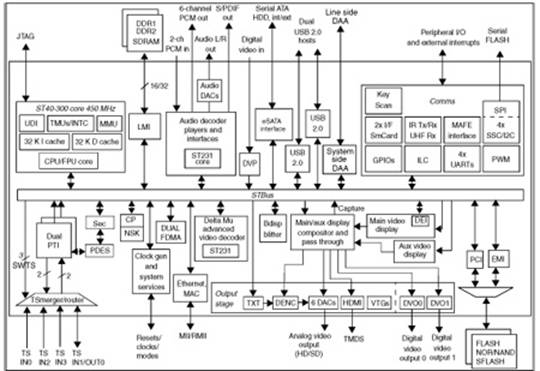
图1. ST7570方框图 The ST7570 demonstration board has been realized as a useful tool which exploits the performance capability of the ST7570 S-FSK power line networking system-on-chip . With this demonstration board, it is possible to evaluate the ST7570 features and its transmitting and receiving performance directly on the power line. The coupling interface is designed to allow the ST7570 device to transmit and receive on the mains using a spread-spectrum FSK signal with 63.3 and 74 kHz tone frequencies, within the European CENELEC EN50065-1 standard A-band, specified for automatic meter reading. 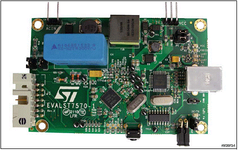
图2. ST7570演示板外形图 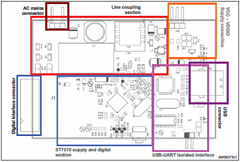
图3. ST7570演示板各部分分割图 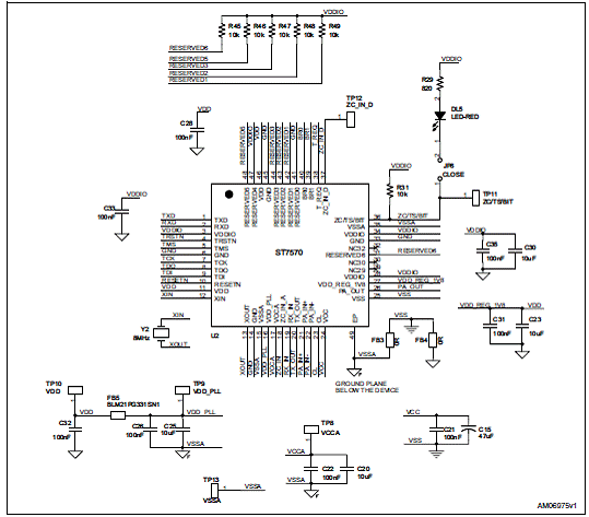
图4. ST7570演示板电路图:ST7570电路图(1) 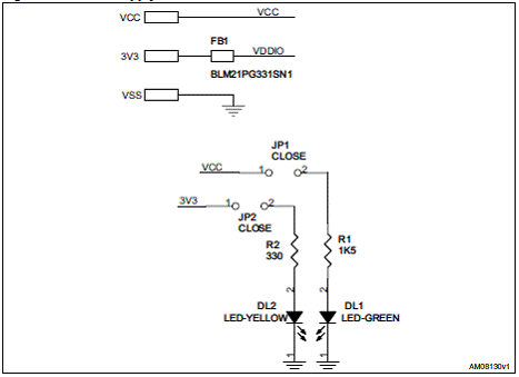
图5. ST7570演示板电路图:电源部分 
图6. ST7570演示板电路图:UART接口部分 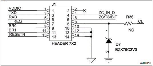
图7. ST7570演示板电路图:外接MCU连接部分 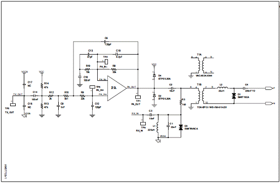
图8. ST7570演示板电路图:ST7570电路 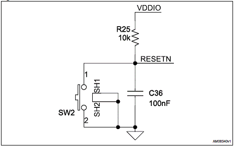
图9. ST7570演示板电路图:复位电路部分 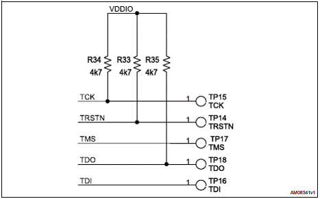
图10. ST7570演示板电路图:JTAG线路 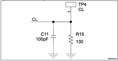
图11. ST7570演示板电路图:限流设定 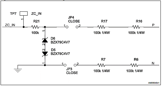
图12. ST7570演示板电路图:非隔离的零交叉 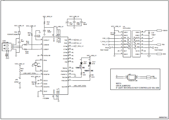
图13. ST7570演示板电路图:USB和UART连接 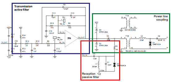
图14. ST7570演示板电路图:接收和发送滤波电路 ST7570演示板材料清单: 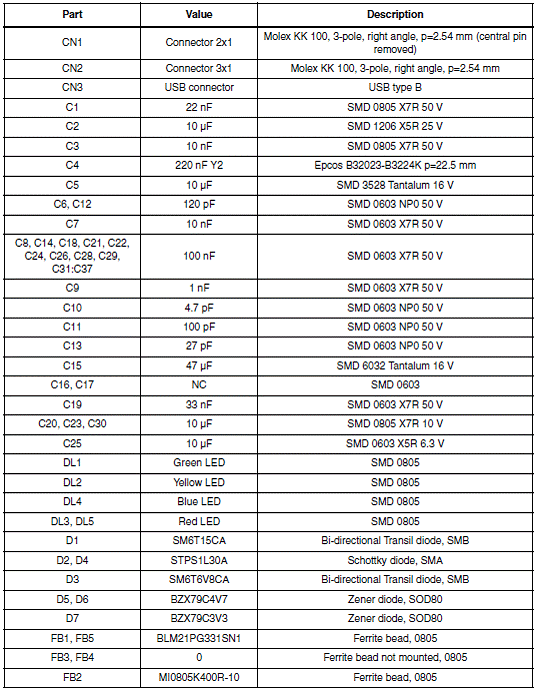
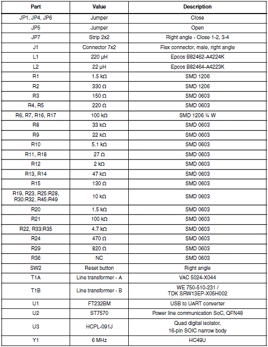
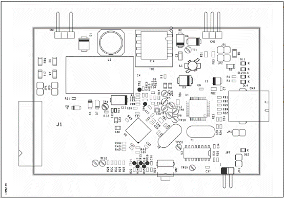
图15. ST7570演示板PCB元件布局图 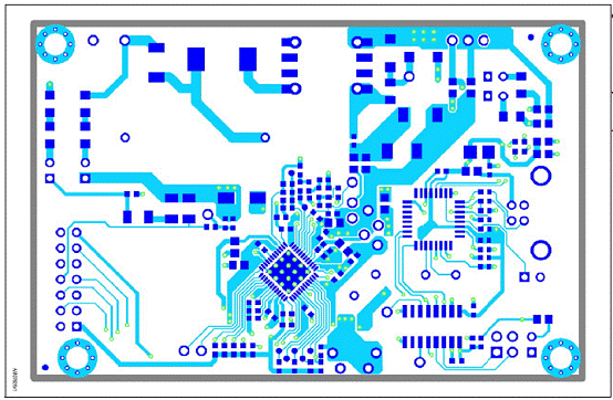
图16. ST7570演示板PCB布局图:顶层 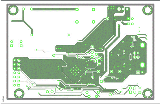
图17. ST7570演示板PCB布局图:底层 详情请见:  CD00271738[1].pdf
(2.1 MB)
 CD00286479[1].pdf
(2.47 MB)
 CD00274120[1].pdf
(617.53 KB)
来源:网络 |


网友评论