Freescale TWR-K40X256 Tower系统开发评估方案
发布时间:2011-7-6 17:02
发布者:Liming
|
Freescale公司的TWR-K40X256采用基于ARM® Cortex™-M4架构的Kinetis K40低功耗MCU,集成了USB 2.0全速OTG和LCD显示控制器,包括有256KB程序闪存和256KB FlexMemory非易失存储器,以及模拟,通信,时序和控制接口,主要用在血糖仪,GPS接收器, 点钞机和自行车码表.本文介绍了K40 MCU系列主要特性,方框图, TWR-K40X256 Tower控制器模块主要特性, 方框图和详细电路图. The K40 MCU family is pin, peripheral and software compatible with the K10 MCU family and adds full-speed USB 2.0 On-The-Go with device charge detect capability and a flexible low-power segment LCD controller with support for up to 320 segments. Devices start from 64 KB of flash in 64QFN packages extending up to 512 KB in a 144MAPBGA package with a rich suite of analog, communication, timing and control peripherals. K40 MCU系列主要特性: • Operating Characteristics – Voltage range: 1.71 to 3.6 V – Flash write voltage range: 1.71 to 3.6 V – Temperature range (ambient): -40 to 105℃ •  erformance erformance– Up to 100 MHz ARM Cortex-M4 core with DSP instructions delivering 1.25 Dhrystone MIPS per MHz •Memories and memory interfaces – Up to 512 KB program flash memory on non-FlexMemory devices – Up to 128 KB RAM – Serial programming interface (EzPort) •Clocks – 3 to 32 MHz crystal oscillator – 32 kHz crystal oscillator – Multi-purpose clock generator •System peripherals – 10 low-power modes to provide power optimization based on application requirements – Memory protection unit with multi-master protection – 16-channel DMA controller, supporting up to 64 request sources – External watchdog monitor – Software watchdog – Low-leakage wakeup unit •Security and integrity modules – Hardware CRC module to support fast cyclic redundancy checks – 128-bit unique identification (ID) number per chip •Human-machine interface – Segment LCD controller supporting up to 40 frontplanes and 8 backplanes, or 44 frontplanes and 4 backplanes – Low-power hardware touch sensor interface (TSI) – General-purpose input/output •Analog modules – Two 16-bit SAR ADCs – Programmable gain amplifier (PGA) (up to x64) integrated into each ADC – 12-bit DAC – Three analog comparators (CMP) containing a 6-bit DAC and programmable reference input – Voltage reference •Timers – Programmable delay block – Eight-channel motor control/general purpose/PWM timer – Two 2-channel quadrature decoder/general purpose timers – Periodic interrupt timers 16-bit low-power timer – Carrier modulator transmitter – Real-time clock •Communication interfaces – USB full-/low-speed On-the-Go controller with onchip transceiver – Two Controller Area Network (CAN) modules – Three SPI modules – Two I2C modules – Five UART modules – Secure Digital host controller (SDHC) – I2S module K40 MCU目标应用: GPS receivers Blood glucose meters Bike computers Currency counters 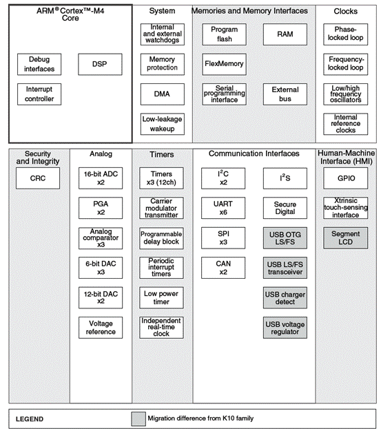
图1.K40 MCU系列方框图 TWR-K40X256 Tower控制器模块 The TWR-K40X256 is a Tower Controller Module compatible with the Freescale Tower System. It can function as a stand-alone, low-cost platform for the evaluation of the Kinetis K30 and K40 family of microcontroller (MCU) devices. The TWRPI-SLCD segment LCD daughter card is included as part of the TWR-K40X256. The TWR-K40X256 features the Kinetis K40 low-power microcontroller based on the ARM® Cortex™-M4 architecture with USB 2.0 full-speed OTG and segment LCD display controllers. The K40X256 includes 256Kbytes of program flash storage and an additional 256Kbytes of FlexMemory non-volatile storage that can be used as additional program flash memory, data flash, or variable size/endurance EEPROM. The TWR-K40X256 is available as a stand-alone product or as a kit (TWR-K40X256-KIT) with the Tower Elevator Modules (TWR-ELEV) and the Tower Serial Module (TWR-SER). The TWR-K40X256 can also be combined with other Freescale Tower peripheral modules to create development platforms for a wide variety of applications. The TWR-K40X256 is a Tower Controller Module featuring the MK40X256VMD100—an ARM Cortex-M4 based microcontroller with segment LCD and USB 2.0 full-speed OTG controllers in a 144 MAPBGA package with a maximum core operating frequency of 100MHz. It is intended for use in the Freescale Tower System but can operate stand-alone. An on-board debug circuit, OSJTAG, provides a JTAG debug interface and a power supply input through a single USB mini-AB connector. 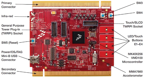
图2.TWR-K40X256 Tower模块外形图 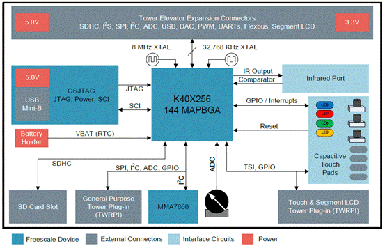
图3.TWR-K40X256 Tower模块方框图 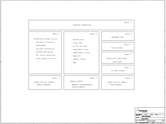
图3.TWR-K40X256 Tower模块电路图(1) 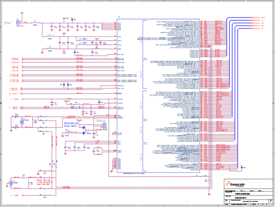
图4.TWR-K40X256 Tower模块电路图(2) 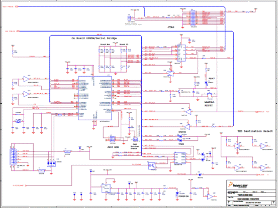
图5.TWR-K40X256 Tower模块电路图(3) 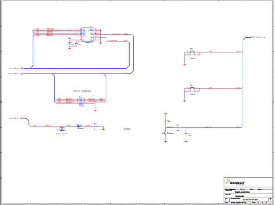
图6.TWR-K40X256 Tower模块电路图(4) 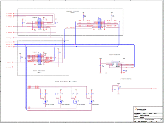
图7.TWR-K40X256 Tower模块电路图(5) 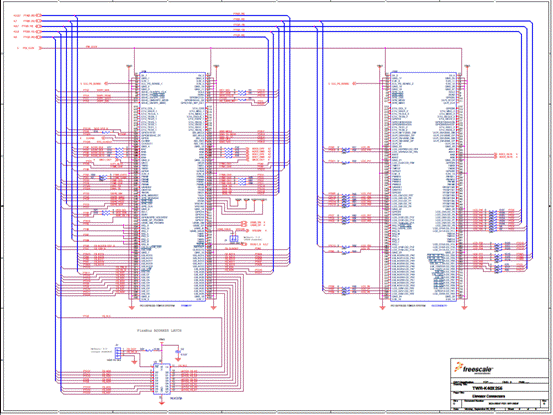
图8.TWR-K40X256 Tower模块电路图(6) 详情请见: http://cache.freescale.com/files/microcontrollers/doc/data_sheet/K40P100M100SF2.pdf?fpsp=1&WT_TYPE=Data Sheets&WT_VENDOR=FREESCALE&WT_FILE_FORMAT=pdf&WT_ASSET=Documentation |


网友评论