ADI ADP1607 2MHz同步升压DC-DC转换器设计方案
发布时间:2013-1-19 19:43
发布者:1770309616
|
ADI公司的ADP1607是一款高效、同步、固定频率、升压型DC/DC转换器,主要应用于便携设备,输出电压可调范围为1.8V至3.3V。该芯片具有2Mhz的固定输出频率、小封装、同步矫正、内部补偿、内部限流、输出隔离、热关断、优秀的瞬态响应和外围器件少等特点。本文通过总结ADP1607器件的特点,介绍器件、特性、应用方向及内部结构框图,并给参考设计实例主要特性、原理图、制板图及元器件清单。 The ADP1607 is a high efficiency, synchronous, fixed frequency, step-up dc-to-dc switching converter with an adjustable output voltage between 1.8 V and 3.3 V for use in portable applications. The 2 MHz operating frequency enables the use of small footprint, low profile external components. Additionally, the synchronous rectification, internal compensation, internal fixed current limit, and current mode architecture allow for excellent transient response and a minimal external part count. Other key features include fixed PWM and light load PFM mode options, true output isolation, thermal shutdown (TSD), and logic controlled enable. Available in a lead-free, thin, 6-lead LFCSP package, the ADP1607 is ideal for providing efficient power conversion in portable devices. ADP1607主要特性: Up to 96% efficiency 0.8 V to VOUT input voltage range Low 0.9 V input start-up voltage 1.8 V to 3.3 V output voltage range 23 μA quiescent current Fixed PWM and light load PFM mode options Synchronous rectification True shutdown output Isolation Internal soft start, compensation, and current limit 2 mm × 2 mm, 6-lead LFCSP Compact solution size ADP1607应用: 1-cell and 2-cell alkaline and NiMH/NiCd powered devices Portable audio players, instruments, and medical devices Solar cell applications Miniature hard disk power supplies Power LED status indicators 
图1. ADP1607方框图 ADP1607参考设计主要特性: 0.8 V to VOUT input voltage range Low 0.9 V input start-up voltage Fixed 2 MHz PWM and light load PFM mode options Auto PFM/PWM transition modes (ADP1607-EVALZ) PWM mode only (ADP1607-001-EVALZ) 3.3 V output voltage Jumper for enable/shutdown control R1 and R2 selected for VOUT = 3.3 V output voltages ADP1607设计原理图: 
图2. ADP1607设计原理图 ADP1607设计方案材料清单: 
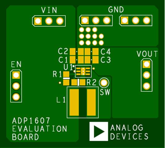
PCB元件布局图: 

 ADP1067.pdf
(452.05 KB)
 UG-488.pdf
(151.56 KB)
(网络) |


网友评论