TI ADS131E08 24位低功耗模拟前端(AFE)解决方案
发布时间:2012-7-25 12:39
发布者:1770309616
|
TI 公司的ADS131E08是24位低功耗模拟前端(AFE),内置可编增益放大器(PGA),基准电源和振荡器,具有工业电源监视,控制和保护等功能.ADS131E0x有八个差分电流和电压输入,1 kSPS时的动态范围118dB,串扰-110dB,50Hz和60Hz的THD为-90dB,主要用在能量计量,电源监视,控制和保护等.本文介绍了ADS131E0x主要特性,方框图,典型应用电路图,以及功率监视系统框架图,ADS131E08EVM-PDK评估板主要特性,电路图,材料清单和PCB元件布局图. The ADS131E0x are a family of multichannel, simultaneous sampling, 24- and 16-bit, delta-sigma (ΔΣ), analog-to-digital converters (ADCs) with a built-in programmable gain amplifier (PGA), internal reference, and an onboard oscillator. The ADS131E0x incorporate features commonly required in industrial power monitoring, control, and protection applications. The ADS131E0x inputs can be independently and directly interfaced with a resistor-divider network or a transformer to measure voltage. The inputs can also be interfaced to a current transformer or Rogowski coil to measure current. With high integration levels and exceptional performance, the ADS131E0x family enables the creation of scalable industrial power systems at significantly reduced size, power, and low overall cost. The ADS131E0x have a flexible input multiplexer per channel that can be independently connected to the internally-generated signals for test, temperature, and fault detection. Fault detection can be implemented internal to the device, using the integrated comparators with digital-to-analog converter (DAC)-controlled trigger levels. The ADS131E0x can operate at data rates as high as 64 kSPS. These complete analog front-end (AFE) solutions are packaged in a TQFP-64 package and are specified over the industrial temperature range of –40℃ to +105℃ ADS131E0x主要特性: Eight Differential Current and Voltage Inputs Outstanding Performance: Exceeds Class 0.1 Performance Dynamic Range at 1 kSPS: 118 dB Crosstalk: –110 dB THD: –90 dB at 50 Hz and 60 Hz Supply Range: Analog:+3 V to +5 V (Unipolar)±2.5 V (Bipolar, allows dc coupling) Digital: +1.8 V to +3.6 V Low Power: 2 mW per Channel Data Rates: 1, 2, 4, 8, 16, 32, and 64 kSPS Programmable Gains (1, 2, 4, 8, and 12) Fault Detection and Device Testing Capability SPI™ Data Interface and Four GPIOs Package: TQFP-64 (PAG) Operating Temperature Range: –40℃ to +105℃ ADS131E0x应用: Industrial Power Applications: Energy Metering Monitoring, Control, and Protection 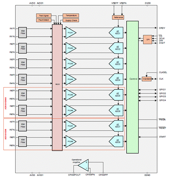
图1.ADS131E0x系列框图 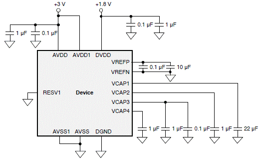
图2.ADS131E0x系列单电源工作电路图 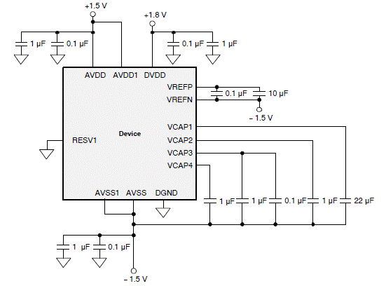
图3.ADS131E0x系列双电源工作电路图 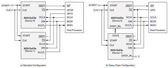
图4.ADS131E0x系列多个器件配置图 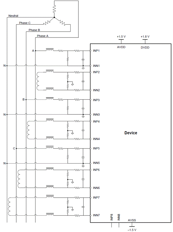
图5.ADS131E0x系列功率监视系统框架图 ADS131E08EVM-PDK评估板 This user’s guide describes the characteristics, operation, and use of the ADS131E08EVM-PDK. This performance demonstration kit is an evaluation module for the ADS131E08, an eight-channel, 24-bit, lowpower, integrated analog front-end (AFE) designed for power protection circuits. The ADS131E08EVMPDK is intended for prototyping and evaluation. This user’s guide includes a complete circuit description,schematic diagram, and bill of materials. The ADS131E08EVM-PDK is a demonstration kit for the ADS131E08, a simultaneous sampling, 24-bit, delta-sigma (Δ Σ) analog-to-digital converter (ADC) with a built-in programmable gain amplifier (PGA), internal reference, and an onboard oscillator. The ADS131E08 contains the features commonly required for industrial power monitoring and control but has the flexibility to fit a variety of applications which require an eight channel, 24-bit ADC. The ADS131E08EVM-PDK demonstration kit is designed to expedite evaluation and system development. ADS131E08EVM-PDK评估板主要特性: Easy-to-use evaluation software for Microsoft™ Windows XP or Windows 7 Built-in analysis tools including oscilloscope, FFT, and histogram displays Flexible input configurations Optional external reference circuits Ability to export data in simple test files for post processing 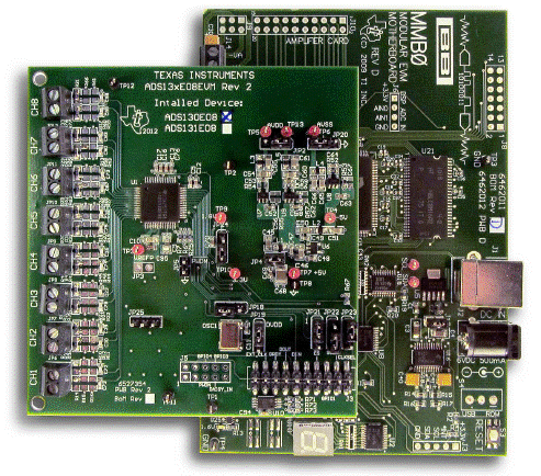
图6.ADS131E08EVM-PDK评估板外形图 
图7.ADS131E08EVM-PDK评估板电路图(1) 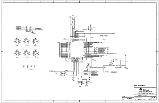
图8.ADS131E08EVM-PDK评估板电路图(2) 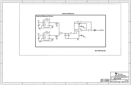
图9.ADS131E08EVM-PDK评估板电路图(3) 
图10.ADS131E08EVM-PDK评估板电路图(4) 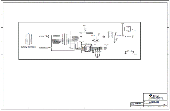
图11.ADS131E08EVM-PDK评估板电路图(5) ADS131E08EVM-PDK评估板材料清单: 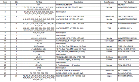
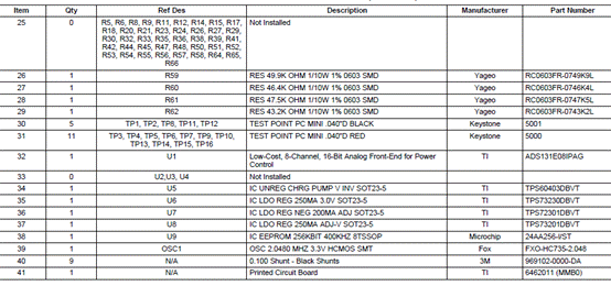

图12.ADS131E08EVM-PDK评估板PCB元件布局图(顶层) 
图13.ADS131E08EVM-PDK评估板PCB元件布局图(底层) 详情请见:  sbas561.pdf
(1.66 MB)
和  sbau200.pdf
(1.95 MB)
来源:网络 |


网友评论