Keil Toshiba TMPM360F20FG ARM Cortex-M3 MCU开发方案
发布时间:2012-6-29 11:14
发布者:1770309616
|
Toshiba 公司的TMPM360F20FG是基于ARM Cortex-M3 的32位MCU,集成了2048KB Flash ROM和128KB SRAM,时钟高达64MHz,具有四路存储器控制器,1路Watchdoc计时器,12路UART,5路I2C,1路CEC,1路遥控信号处理器,97个中断,120 GPIO引脚,待机模式,时钟发生器和片上调试(SWD,ETM),主要用于MCU市场.而Keil公司的MCBTMPM360评估板为你提供了创建和测试基于ARM Cortex-M3的TMPM360系列的工作程序.本文介绍了Cortex-M3处理器主要特性和优势,框图,TMPM360F20FG方框图和主要特性,以及MCBTMPM360评估板主要特性,框图和电路图. The Toshiba TMPM360F20FG is a Cortex-M3 based Microcontroller, 2048KB Flash ROM, 128KB SRAM, clock up to 64MHz, 4 channels Memory Controller, 2 channels DMA Controller 16 channels 16-bit Timer, 1 channel Real timer clock, 1 channel Watchdoc Timer, 12 channels UART, 5 channels I2C, 1 channel CEC, 1 channel Remote Control Signal Preprocessor, 97 Interrupts, 120 GPIO Pins, Standby mode, Clock generator (PLL), and On-Chip debugging (SWD, ETM). The Cortex-M3 processor is a high performance 32-bit processor designed for the microcontroller market. It offers significant benefits to developers, including: • outstanding processing performance combined with fast interrupt handling • enhanced system debug with extensive breakpoint and trace capabilities • efficient processor core, system and memories • ultra-low power consumption with integrated sleep mode and an optional deep sleep Mode • platform security robustness, with an optional integrated Memory Protection Unit (MPU). The Cortex-M3 processor is built on a high-performance processor core, with a 3-stage pipeline Harvard architecture, making it ideal for demanding embedded applications. The processor delivers exceptional power efficiency through an efficient instruction set and extensively optimized design, providing high-end processing hardware including optional IEEE754-compliant single-precision floating-point computation, a range of single-cycle and SIMD multiplication and multiply-with-accumulate capabilities, saturating arithmetic and dedicated hardware division. To facilitate the design of cost-sensitive devices, the Cortex-M3 processor implements tightly-coupled system components that reduce processor area while significantly improving interrupt handling and system debug capabilities. The Cortex-M3 processor implements a version of the Thumb® instruction set based on Thumb-2 technology, ensuring high code density and reduced program memory requirements. The Cortex-M3 instruction set provides the exceptional performance expected of a modern 32-bit architecture, with the high code density of 8-bit and 16-bit microcontrollers. The Cortex-M3 processor closely integrates a configurable NVIC, to deliver industry-leading interrupt performance. The NVIC includes a Non-Maskable Interrupt (NMI) that can provide up to 256 interrupt priority levels. The tight integration of the processor core and NVIC provides fast execution of Interrupt Service Routines (ISRs), dramatically reducing the interrupt latency. Cortex-M3处理器主要特性和优势: • tight integration of system peripherals reduces area and development costs • Thumb instruction set combines high code density with 32-bit performance • code-patch ability for ROM system updates • power control optimization of system components • integrated sleep modes for low power consumption • fast code execution permits slower processor clock or increases sleep mode time • hardware division and fast digital-signal-processing orientated multiply accumulate • deterministic, high-performance interrupt handling for time-critical applications • optional MPU for safety-critical applications • extensive implementation-defined debug and trace capabilities: — Serial Wire Debug and Serial Wire Trace reduce the number of pins required for debugging, tracing, and code profiling. 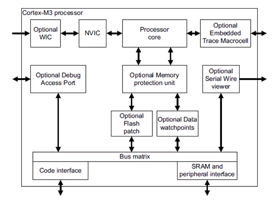
图1.Cortex-M3处理器框图 TMPM360F20FG主要特性: ARM® Cortex-M3 CPU Core Operating voltage: 2.7 to 3.6V (Single supply) Maximum operating frequency: 64 MHz (8 MHz x 8 by PLL) Built-in Functions DMA controller: 2 channels Memory controller: 1 channel Chip Select/Wait controller: 4 channels 10-bit DA converter : 2 channels 16-bit timer: 16 channels SIO/UART: 12 channels I2C/SIO: 5 channels SSP (SPI/MicroWire mode): 1 channel RTC: 1 channel CEC: 1 channel Remote control signal preprocessor: 2 channels Debug circuit (SWD/SWV): 1 channel Trace function (ETM): 4-bit 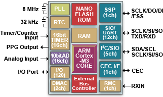
图2.TMPM360F20FG方框图 MCBTMPM360评估板 The Keil MCBTMPM360 Evaluation Boards enable you to create and test working programs based on the Toshiba TMPM360 family of ARM Cortex-M3 processor-based devices. The MCBTMPM360 Evaluation Board is available in two configurations: The MCBTMPM362 Evaluation Board is populated with a Toshiba TMPM362F10 device The MCBTMPM364 Evaluation Board is populated with a Toshiba TMPM364F10 device providing the additional functionality of CAN and USB MCBTMPM360评估板主要特性: 64MHz ARM Cortex-M3 processor-based MCU in 144-pin LQFP On-Chip Flash: 1MB (TMPM362/TMPM364) On-Chip RAM: 64KB (TMPM362/TMPM364) USB 2.0 Host (TMPM364 only) CAN 2.0 Interface (TMPM364 only) UART, I2C, and 120 GPIO via PCB headers Potentiometer for ADC Input 5 LEDs and 6 push-buttons Power via USB connector Debug Interface Connectors 10-pin Cortex debug (0.05 inch connector) 20-pin Cortex debug + ETM Trace (0.05 inch connector) MCBTMPM360/2/4评估板技术指标:
You may use the Cortex-M3 based MCBTMPM360 Evaluation Boards to generate and test application programs for the Toshiba TMPM360Fxxx microcontroller family. With this hands-on process, you can determine the hardware and software requirements for current and future product development. This board is available in two variants: the MCBTMPM360 and the MCBTMPM364. The MCBTMPM360 is populated with the Toshiba TMPM360F20FG microcontroller. The MCBTMPM364 is populated with the Toshiba TMPM364F10FG microcontroller. The MCBTMPM364 board has more RAM and Flash memory than the MCBTMPM360 board, and supports USB Host and CAN interfaces. 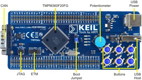
图3.MCBTMPM360评估板外形图 MCBTMPM360评估板主要特性: USB 2.0 Full Speed Interface A standard USB "A" connector for applications requiring USB Host capabilities. CAN Port A standard DB9 connector for applications requiring CAN communications. Analog Voltage Control for ADC Input An adjustable analog voltage source for testing the Analog to Digital converter built into the TMPM360F20FG. Cortex/ETM Download and Debug The MCBTMPM360 board incorporates both a JTAG interface and a Cortex Debug + ETM interface. When coupled with the ULINK2 USB-JTAG adapter, the 10-pin Serial Wire JTAG interface allows flash programming and debugging. With the ULINKPro adapter, the 20-pin Cortex Debug/ETM interface allows flash programming and instruction trace debugging. MCBTMPM360 board components. 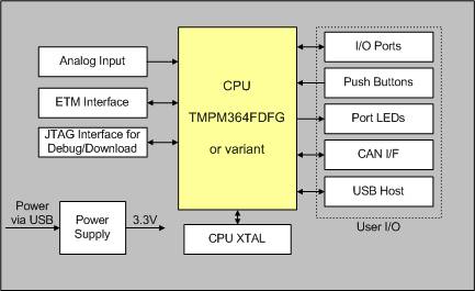
图4.MCBTMPM360评估板方框图 MCBTMPM360评估板技术数据:
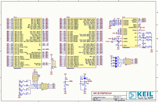
图5.MCBTMPM360评估板电路图(1) 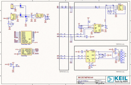
图6.MCBTMPM360评估板电路图(2) 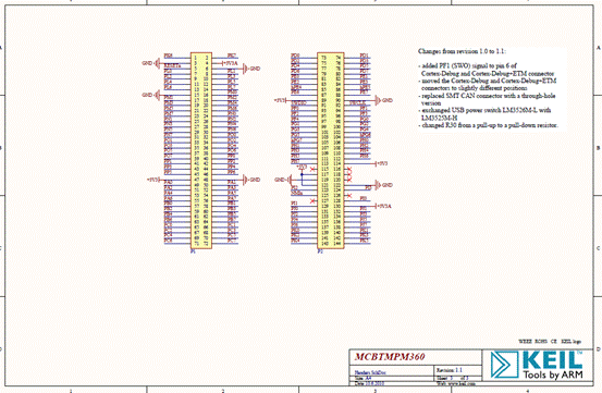
图7.MCBTMPM360评估板电路图(3) 详情请见:  dui0552a_cortex_m3_dgug[1].pdf
(1.3 MB)
 mcbtmpm360_schematics[1].pdf
(979.86 KB)
来源:网络 | |||||||||||||||||||||||||||||||||||||||||||||||||||||||||||||||||||||||||||||||||||||||||||||||||||||||||||||||||||||||||||||||||||||||||



网友评论