Lattice LPTM10-12107混合信号平台管理方案
发布时间:2011-7-28 11:54
发布者:Liming
|
Lattice公司的平台管理器件系列代表了第三代混合信号器件,可编称程的平台管理器件由于集成可编程的模拟和逻辑,支持众多的共同功能如功率管理,数字管理和胶合逻辑,大大简化了板的管理,不仅降低了成本,还提高系统可靠性,提供了设计高度灵活性.本文介绍了LPTM10-12107平台管理器件主要特性,方框图, 典型应用框图和平台管理开发板电路图与材料清单. The Lattice Platform Manager integrates board power management (hot-swap, sequencing, monitoring, reset generation, trimming and margining) and digital board management functions (reset tree, non-volatile error logging, glue logic, board digital signal monitoring and control, system bus interface, etc.) into a single integrated solution. The Platform Manager device provides 12 independent analog input channels to monitor up to 12 power supply test points. Up to 12 of these input channels can be monitored through differential inputs to support remote ground sensing. Each of the analog input channels is monitored through two independently programmable comparators to support both high/low and in-bounds/ out-of-bounds (window-compare) monitor functions. Up to six general purpose 5V tolerant digital inputs are also provided for miscellaneous control functions. There are 16 open-drain digital outputs that can be used for controlling DC-DC converters, low-drop-out regulators (LDOs) and opto-couplers, as well as for supervisory and general purpose logic interface functions. Four of these outputs (HVOUT1-HVOUT4) may be configured as high-voltage MOSFET drivers. In highvoltage mode these outputs can provide up to 12V for driving the gates of n-channel MOSFETs so that they can be used as high-side power switches controlling the supplies with a programmable ramp rate for both ramp up and ramp down. Features Precision Voltage Monitoring Increases Reliability • 12 independent analog monitor inputs • Differential inputs for remote ground sense • Two programmable threshold comparators per analog input • Hardware window comparison • 10-bit ADC for I2C monitoring High-Voltage FET Drivers Enable Integration • Power supply ramp up/down control • Programmable current and voltage output • Independently configurable for FET control or digital output Power Supply Margin and Trim Functions • Trim and margin up to eight power supplies • Dynamic voltage control through I2C • Independent Digital Closed-Loop Trim function for each output Programmable Timers Increase Control Flexibility • Four independent timers • 32 us to 2 second intervals for timing sequences PLD Resources Integrate Power and Digital Functions • 48-macrocell CPLD • 640 LUT4s FPGA • Up to 107 digital I/Os • Up to 6.1 Kbits distributed RAM Programmable sysIO™ Buffer Supports a Range of Interfaces • LVCMOS 3.3/2.5/1.8/1.5/1.2 • LVTTL System-Level Support • Single 3.3V supply operation • Industrial temperature range: -40°C to +85°C In-System Programmability Reduces Risk • Integrated non-volatile configuration memory • JTAG programming interface Package Options • 128-pin TQFP • 208-ball ftBGA • RoHS compliant and halogen-free 
图1a. LPTM10-12107方框图 The Platform Manager™ product family represents the third-generation of mixed-signal devices available from Lattice. Programmable Platform Manager devices simplify board management design significantly by integrating programmable analog and logic to support many common functions, such as power management, digital housekeeping and glue logic. By integrating these support functions, Platform Manager devices not only reduce the cost of these functions compared to traditional approaches, but also improve system reliability and provide a high degree of design flexibility that minimizes the risk of circuit board re-spins. Using the preloaded Board Digital Management design provided with the development kit, you can test within minutes power management functions such as power supply hot swap control, redundant supply selection and payload power management. Digital management support functions include reset distribution, system interfacing, power-on configuration and fault monitoring and logging. The kit also demonstrates enhanced power management features such as power supply closed loop trimming and margining. Power for the board comes from a 12VDC wall plug supply. This user’s guide describes how to start using the Platform Manager Development Kit, an easy-to-use system for evaluating and designing with the Platform Manager mixed-signal device. The kit serves as a development test environment to build designs for power supply man agement functions such as sequencing, power supply fault logging, trimming, reset generation, high-side MOSFET drive and user logic I/O expansion in an FPGA. LPTM10-12107平台管理开发板主要特性: The Platform Manager Development Kit includes: • Platform Manager Evaluation Board containing the Platform Manager LPTM10-12107 device in a 208-ball ftBGA package • USB programming support on-board • 4Mbit SPI Flash memory for logging data and faults • SPI and I2C interfaces • 2x16 expansion header for I2C, SPI and general purpose data bus, I/O • Two 4-bit DIP switches • Three push-buttons for input control, reset, etc. • DAC and A/D convertors for trimming power supplies • LED displays • LCD display • Adjustable potentiometers for user faults or demos • Thermistor circuit for temperature sensing • LDO to demo sequencing and trim functions • DC-DC convertor to demo sequencing and trim functions • Two LDOs for main chip power and VCCIO supplies. • VMON, voltage monitors for on-board and off-board power supply monitoring • Off-board screw connectors for user loads and testing • Prototyping/interface connections • Pre-loaded Demo – The Platform Manager Development Kit contains a pre-loaded demo design that illustrates many of the key features of the Platform Manager device. • USB Connector Cable – The Platform Manager Evaluation Board is programmed via the USB cable driven from the user’s computer. This USB cable is included in the Platform Manager Development Kit. • Power Supply – The Platform Manager Evaluation board is powered by an AC adapter (included). • Platform Manager Development Kit QuickSTART Guide – Provides information on connecting the Platform Man-ager Evaluation Board, getting started with the pre-programmed demo, and starting your own design. • Platform Manager Development Kit Web Page – The Platform Manager Development Kit Web Page provides access to the latest documentation, demo designs and additional resources. 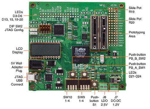
图1b.LPTM10-12107平台管理评估板外形图 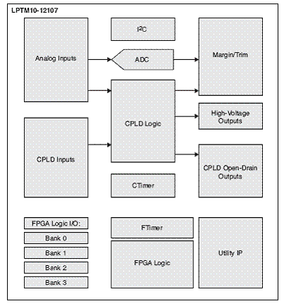
图2.LPTM10-12107平台管理开发板方框图 Platform Manager is shown below in a board application where it is providing power management functions to detect faults across up to 12 supplies, margin and trim up to 8 supplies, capture and integrate 12V hot swap. It is also providing digital support including log information to NV memory, flexible reset distribution and configuration of payload ICs at power-on. 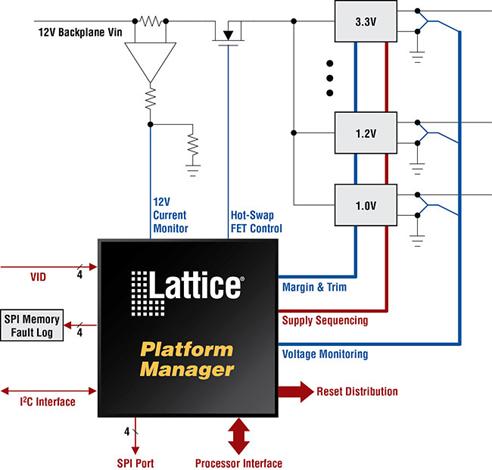
图3.LPTM10-12107平台管理的典型应用框图 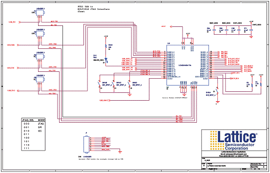
图4.LPTM10-12107平台管理开发板电路图:Mux 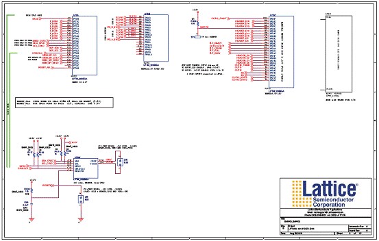
图5.LPTM10-12107平台管理开发板电路图:Bank0, Bank3 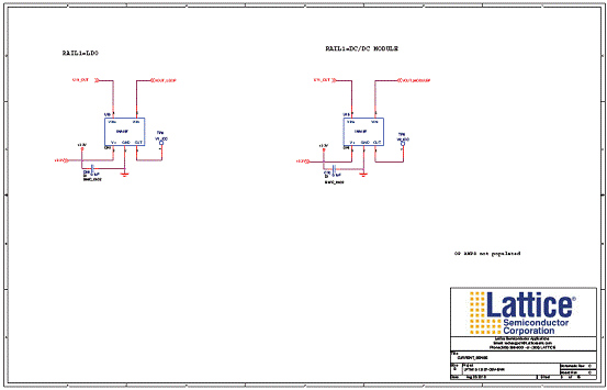
图6.LPTM10-12107平台管理开发板电路图  PTM10-12107-DEC-EVN PTM10-12107-DEC-EVN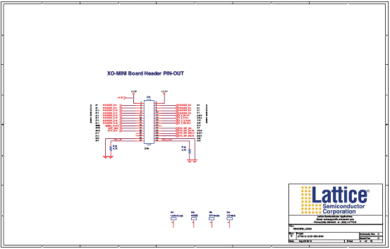
图7.LPTM10-12107平台管理开发板电路图:Headers Logo 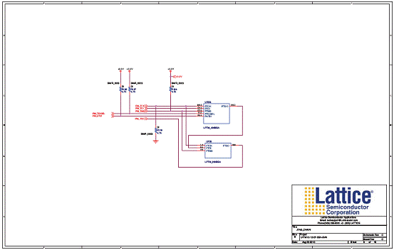
图8.LPTM10-12107平台管理开发板电路图:JTAG链 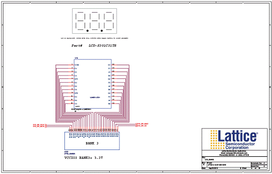
图9.LPTM10-12107平台管理开发板电路图: LCD Bank3 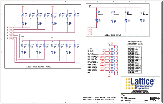
图10.LPTM10-12107平台管理开发板电路图  ED ED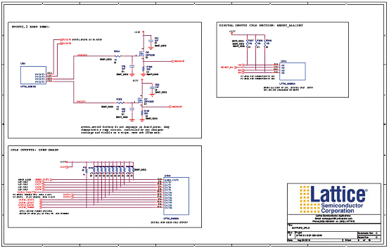
图11.LPTM10-12107平台管理开发板电路图:CPLD输出 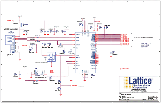
图12.LPTM10-12107平台管理开发板电路图:USB部分 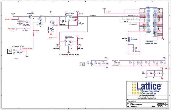
图13.LPTM10-12107平台管理开发板电路图:板电源 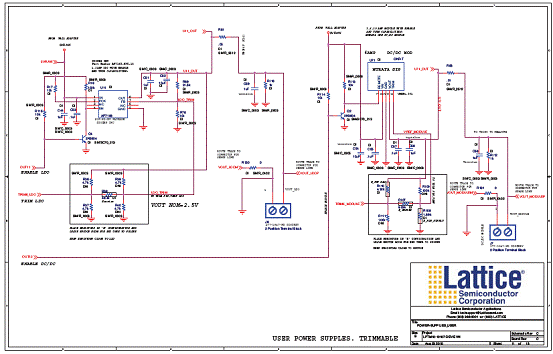
图14.LPTM10-12107平台管理开发板电路图:用户电源 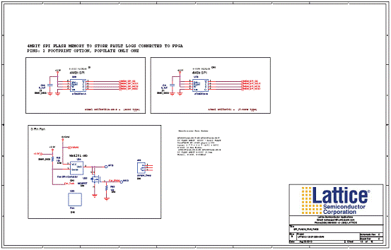
图15.LPTM10-12107平台管理开发板电路图:SPI Flash Fan Pad 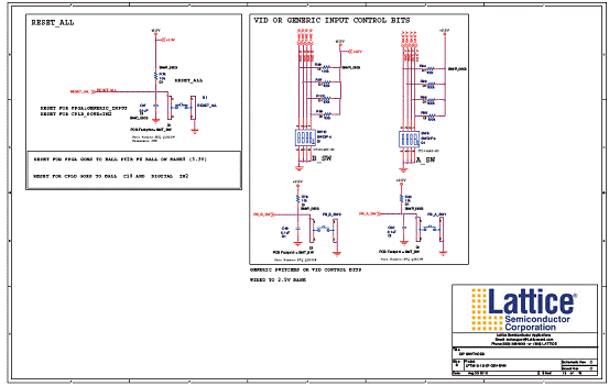
图16.LPTM10-12107平台管理开发板电路图  IP开关 IP开关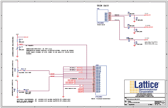
图17.LPTM10-12107平台管理开发板电路图:VMON,DAC和滑动电位计 LPTM10-12107平台管理开发板材料清单: 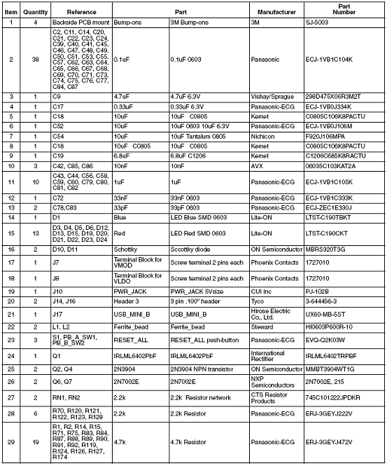
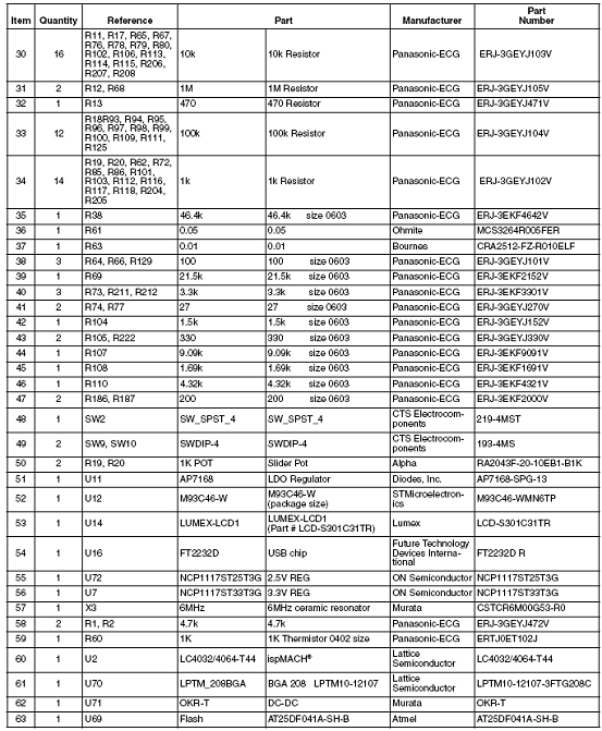
详情请见:  DS1036[1].pdf
(2 MB)
 EB58[1].pdf
(1.56 MB)
|


网友评论