
Maxim MAXQ610КЭMAX7032ЫЎБэздЖЏЖСБэ(AMR)ВЮПМЩшМЦ
ЗЂВМЪБМфЃК2012-5-14 17:38
ЗЂВМепЃК1770309616
|
MaximЙЋЫОЕФЫЎБэздЖЏЖСБэ(AMR)ВЮПМЩшМЦLFRD003ВЩгУДјКьЭтФЃПщЕФMAXQ610ЕЭЙІКФ16ЮЛMAXQЮЂПижЦЦїКЭMAX7032ЛљгкОЇеёЕФЗжЪ§NЪеЗЂЦї,ЬсЙЉСЫЪЙгУЙЄвЕ/ПЦбЇ/вНСЦЩфЦЕ(ISM-RF)ЕФЭъећЦНЬЈ,ПЩвдЪЕЯжЫЎБэAMRЕФЩшМЦ.БОЮФНщЩмСЫMAXQ610КЭMAX7032жївЊЬиад, ЫЎБэздЖЏЖСБэ(AMR)ВЮПМЩшМЦжївЊЬиадвдМАRFФЃПщгыЪжГжНгПк (HHI)ВПЗжЕчТЗЭМ,ЯргІЕФВФСЯЧхЕЅКЭPCBВМОжЭМ. The MAXQ610 is a low-power, 16-bit MAXQ® microcontroller designed for low-power applications including universal remote controls, consumer electronics, and white goods. The MAXQ610 combines a powerful 16-bit RISC microcontroller and integrated peripherals including two USARTs and an SPI™ master/slave communications port, along with an IR module with carrier frequency generation and flexible port I/O capable of multiplexed keypad control. The MAXQ610 includes 64KB of flash memory and 2KB of data SRAM. Intellectual property (IP) protection is provided by a secure MMU that supports multiple application privilege levels and protects code against copying and reverse engineering. Privilege levels enable vendors to provide libraries and applications to execute on the MAXQ610, while limiting access to only data and code allowed by their privilege level. For the ultimate in low-power battery-operated performance, the MAXQ610 includes an ultra-low-power stop mode (0.2ІЬA, typ). In this mode, the minimum amount of circuitry is powered. Wake-up sources include external interrupts, the power-fail interrupt, and a timer interrupt. The microcontroller runs from a wide 1.70V to 3.6V operating voltage. MAXQ610жївЊЬиад: ♦ High-Performance, Low-Power 16-Bit RISC Core ♦ DC to 12MHz Operation Across Entire Operating Range ♦ 1.70V to 3.6V Operating Voltage Range ♦ 33 Total Instructions for Simplified Programming ♦ Three Independent Data Pointers Accelerate Data Movement with Automatic Increment/Decrement ♦ Dedicated Pointer for Direct Read from Code Space ♦ 16-Bit Instruction Word, 16-Bit Data Bus ♦ 16 x 16-Bit General-Purpose Working Registers ♦ Secure MMU for Application Partitioning and IP Protection ♦ Memory Features 64KB Flash: 512 Byte Sectors 20,000 Erase/Write Cycles per Sector Masked ROM Available 2KB Data SRAM ♦ Additional Peripherals Power-Fail Warning Power-On Reset/Brownout Reset Automatic IR Carrier Frequency Generation and Modulation Two 16-Bit, Programmable Timers/Counters with Prescaler and Capture/Compare SPI and Two USART Communication Ports Programmable Watchdog Timer 8kHz Nanopower Ring Oscillator Wake-Up Timer Up to 24 (MAXQ610A) or 32 (MAXQ610B) General-Purpose I/Os ♦ Low-Power Consumption 0.2ІЬA (typ), 2.0ІЬA (max) in Stop Mode TA = +25ЁуC, Power-Fail Monitor Disabled 3.75mA (typ) at 12MHz in Active Mode MAXQ610гІгУ: Remote Controls Battery-Powered Portable Equipment Consumer Electronics Home Appliances White Goods The MAX7032 crystal-based, fractional-N transceiver is designed to transmit and receive ASK/OOK or FSK data in the 300MHz to 450MHz frequency range with data rates up to 33kbps (Manchester encoded) or 66kbps (NRZ encoded). This device generates a typical output power of +10dBm into a 50ІИ load, and exhibits typical sensitivities of -114dBm for ASK data and -110dBm for FSK data. The MAX7032 features separate transmit and receive pins (PAOUT and LNAIN) and provides an internal RF switch that can be used to connect the transmit and receive pins to a common antenna. The MAX7032 transmit frequency is generated by a 16-bit, fractional-N, phase-locked loop (PLL), while the receiverЁЏs local oscillator (LO) is generated by an integer-N PLL. This hybrid architecture eliminates the need for separate transmit and receive crystal reference oscillators because the fractional-N PLL allows the transmit frequency to be set within 2kHz of the receive frequency. The 12-bit resolution of the fractional-N PLL allows frequency multiplication of the crystal frequency in steps of fXTAL/4096. Retaining the fixed-N PLL for the receiver avoids the higher current drain requirements of a fractional-N PLL and keeps the receiver current drain as low as possible. The fractional-N architecture of the MAX7032 transmit PLL allows the transmit FSK signal to be programmed for exact frequency deviations, and completely eliminates the problems associated with oscillator-pulling FSK signal generation. All frequency-generation components are integrated on-chip, and only a crystal, a 10.7MHz IF filter, and a few discrete components are required to implement a complete antenna/digital data solution. The MAX7032 is available in a small 5mm x 5mm, 32-pin, thin QFN package, and is specified to operate in the automotive -40ЁуC to +125ЁуC temperature range. MAX7032жївЊЬиад: ♦ +2.1V to +3.6V or +4.5V to +5.5V Single-Supply Operation ♦ Single Crystal Transceiver ♦ User-Adjustable 300MHz to 450MHz Carrier Frequency ♦ ASK/OOK and FSK Modulation ♦ User-Adjustable FSK Frequency Deviation Through Fractional-N PLL Register ♦ Agile Transmitter Frequency Synthesizer with fXTAL/4096 Carrier-Frequency Spacing ♦ +10dBm Output Power into 50ІИ Load ♦ Integrated TX/RX Switch ♦ Integrated Transmit and Receive PLL, VCO, and Loop Filter ♦ > 45dB Image Rejection ♦ Typical RF Sensitivity ASK: -114dBm FSK: -110dBm ♦ Selectable IF Bandwidth with External Filter ♦ RSSI Output with High Dynamic Range ♦ Autopolling Low-Power Management ♦ < 12.5mA Transmit-Mode Current ♦ < 6.7mA Receive-Mode Current ♦ < 23.5ІЬA Polling-Mode Current ♦ < 800nA Shutdown Current ♦ Fast-On Startup Feature, < 250ІЬs ♦ Small 32-Pin, Thin QFN Package MAX7032гІгУ: 2-Way Remote Keyless Entry Security Systems Home Automation Remote Controls Remote Sensing Smoke Alarms Garage Door Openers Local Telemetry Systems ЫЎБэздЖЏЖСБэ(AMR)ВЮПМЩшМЦ This reference design provides a complete demonstration platform for using industrial/scientific/medical radio frequency (ISM-RF) products in an automatic meter reading (AMR) application. This document includes the hardware, firmware, and system structure requirements for implementing an AMR design that demonstrates operation with a physical water meter. The MAX7032 transceiver reference design (RD) is a self-contained evaluation platform for exercising the device as a wireless automatic meter reading (AMR) and water meter demo system. With the use of the Maxim USB-to-JTAG board (MAXQJTAGUSB), the MAXQ610 on both the handheld interface (HHI) unit and the various meter (MTR) radio modules can be programmed by the end user. The meter board enables basic human interaction through a single momentary switch input and an LED for visual feedback. The MTR is designed to be compact, providing a self-contained transceiver board with a radio, microcontroller, and multiple "ports" for connecting various meter inputs to the system. Two separate designs are provided: one with an MMCX antenna connection, and the other with a small-footprint antenna-mounting option. Input to the MTR system can be configured with up to six ports, and the primary input interfaces with a "pulse" or dry contact (reed) output meter. This board can be operated from any 3V power source (1.7V to 3.6V for the MAXQ610, 2.1V to 3.6V for the MAX7032). The HHI board has seven menu keys for user input, a reset switch, a 102 pixel x 64 pixel LCD display with multicolor LED backlighting for menu interactions, plus a receive signal indicator (RSI) LED. The shape of the HHI fits within a Series 55 BOX enclosure, and has a high-density connector for interfacing with an RF module. Both systems are preprogrammed with operational firmware to demonstrate a simple wireless AMR meter (slave)/reader (master) system. Gerber files are available for simple cut-and-paste designs of the radio sections or the full implementation. ЫЎБэздЖЏЖСБэ(AMR)ВЮПМЩшМЦжївЊЬиад: Proven printed circuit board (PCB) layout Proven component parts list Preprogrammed transceiver (TRX) pair for quick demonstration capabilities Free MAXQ® microcontroller programming tools available for flexible operation The Handheld Interface(HHI) is a two-part system that comprises a human interface board, which contains a LCD display, a key encoder, and a microcontroller. This HHI is mated to an RF module to form a complete handheld communication system. The Phase I design interfaces to a MAX7032 transceiver module through a 10-pin, high-density connector. The Phase III design and the RF modules described later interface through a 60-pin connector. This system interfaces with the RF module through a board-to-board, mezzanine connector using a firmware-defined SPI. The MCU is programmed through an edge connector interface to USB. The power can be supplied through either the edge connector or a wired battery connection. The RF module has an MMCX connector, to which a 6" cable and a reduced-height Linx antenna may be attached, providing a small form factor assembly. 
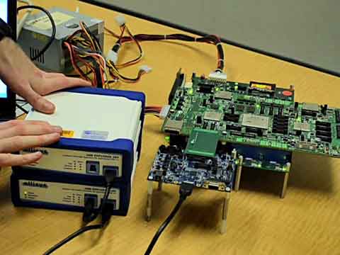
ЭМ1. Phase I HHI КЭRF ФЃПщЭтаЮЭМ 
ЭМ2. Phase III HHI КЭRF ФЃПщЭтаЮЭМ 
ЭМ3.RFФЃПщЗНПђЭМ 
ЭМ4.RFФЃПщЕчТЗЭМ(1) 
ЭМ5.RFФЃПщЕчТЗЭМ(2) RFФЃПщВФСЯЧхЕЅ(BOM): 


ЭМ6. HHI ВПМўЕчТЗЭМ(1) 
ЭМ7. HHI ВПМўЕчТЗЭМ(2) 
ЭМ8. HHI ВПМўЕчТЗЭМ(3) HHI ВПМўВФСЯЧхЕЅ: 

ЭМ9. RFФЃПщPCBВМОжЭМ 
ЭМ10. HHIВПМўPCBВМОжЭМ ЯъЧщЧыМћ:  MAXQ610.pdf
(1.22 MB)
MAX7032.pdf
(301.24 KB)
REFD5404.pdf
(971.58 KB)
MAXQ610.pdf
(1.22 MB)
MAX7032.pdf
(301.24 KB)
REFD5404.pdf
(971.58 KB)
РДдДЃКЭјТч |

ЭјгбЦРТл