
2602型数字源表测试脚本及两个典型命令
发布时间:2012-4-25 18:46
发布者:majake2011
|
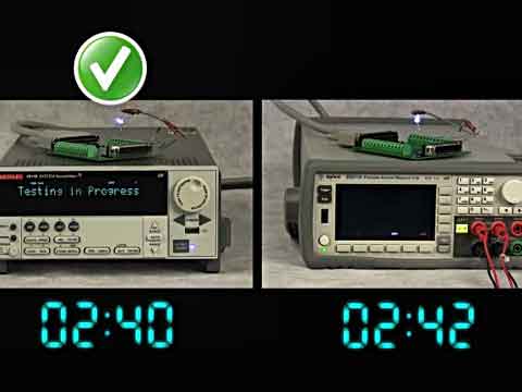
从传统意义上讲,测试工程师将进行测试编程,并将其输入计算机或其他控制器。这类程序可能包括测试执行程序以及函数程序与其他子程序。执行程序通过以适当的顺序来调用不同的函数或子程序,从而控制测试流程。函数和子程序通过向测试系统中的仪器发送命令等对其进行配置并启动测试。它们对数据进行处理和评估,并对待测器件做出通过/失效决策,对数据进行存档。通常,对于每个测试的待测器件来说,控制器都将为各仪器发送命令序列,并不断对得到的数据进行评估。控制器[1]与仪器之间的所有这些通信都可能大大降低测试速度。2600系列测试脚本处理器[2]允许将大部分控制程序下载至数据源表的易失性或非易失性内存。下载至TSP的程序称作脚本。 脚本可能是一个执行多项测试的较长程序。 依照良好的编程规范,可以编写出创建和调用函数的脚本,就像计算机中的控制程序一样。一旦函数建立,就可以通过脚本以及测试脚本处理器中的其他函数中进行调用,或者通过主机控制器中的测试执行程序进行调用。由于参数可以传递至函数,这就提供了一种非常简单的方法,可以轻松的将被测件测试相关参数,如输入信号电平或限值等,从控制器传递至数字源表内部的测试程序中。 在吉时利公司网站(www.keithley.com)可以下载记录详尽的测试DAC脚本示例。这个脚本是全功能的,可以与图3所示的两个2602数字源表一起使用。为了使读者领会新的脚本语言,我们从DAC测试脚本中选取以下代码片段。注意,双点划线(--)表示注释。 让我们看两个典型命令: node[1].smua.source.func = node[1].smua.OUTPUT _ DCVOLTS node[1].smua.source.levelv = 0 脚本语言运行使用别名,这可能使代码更可读,并改进代码执行速度。我们为DAC测试示例定义了以下别名: MASTER = node[1] --Alias indicating control is via Node 1 SLAVE = node[2] --Node 2 is controlled by MASTER via TSP-Link IOUT1 = MASTER.smua --Alias for SMU measuring current output #1 --IOUT1 is equivalent to node[1].smua IOUT2 = MASTER.smub --Alias for SMU measuring current output #2 --IOUT2 is equivalent to node[1].smub DIO = MASTER.digio --Alias for Digital I/O of 2602 #1 --DIO is equivalent to node[1].digio VPLUS = SLAVE.smua --Alias for SMU supplying V+ and measuring current draw --VPLUS is equivalent to node[2].smua VREF = SLAVE.smub --Alias for SMU supplying reference voltage (Vref) --VREF is equivalent to node[2].smub 在整个示例中都使用了别名。利用定义的别名,示例命令可以重写为: IOUT1.source.func = IOUT1.OUTPUT_DCVOLTS IOUT1.source.levelv = 0 通常,脚本语言[3]不需要明确声明变量。根据对其的赋值,它们被声明和定义为 “on the fly”。但表格(也就是数组)除外, 它们必须定义数据类型。所有变量都是全局的,除非明确声明为本地的。在代码片段出现以下“常数”: Vref = 10 --Use +10VDC reference voltage IoutMax = 0.002 --Max expected current output Nplc = 0.001 --Integration time for SMU A-to-D converters (in terms of power line cycles) Nbits = 8 --Number of DAC control bits (digital inputs) Ncodes = 2^Nbits --Number of possible control codes MaxCode = Ncodes - 1 --Decimal equivalent of full-scale code (255 for 8-bit DAC) Lsb = Vref / MaxCode --Nominal value of least significant bit 在开始实际测试序列之前,一般要对仪器进行某些初始设置。在我们的示例中,初始设置包括设置源函数及范围、测量函数及范围、电压检测模式等等。所有这4个源-测量单元[4]的配置都是类似的。对于节点1的SMU A,某些设置命令如下: MASTER.reset() --Reset all Node 1 logical instruments to default settings IOUT1.sense = IOUT1.SENSE_REMOTE --Use REMOTE (4-wire) voltage sensing IOUT1.source.func = IOUT1.OUTPUT_DCVOLTS --Configure SMU to source DCV IOUT1.source.rangev = 0 --Set voltage source ranges; --2602 picks appropriate range based on programmed value IOUT1.source.levelv = 0 --To measure current, source zero volts on lowest range IOUT1.source.limiti = 1.2 * IoutMax --Set current compliance limit (20% over max) IOUT1.measure.nplc = Nplc --Set integration times for all measurements IOUT1.measure.autozero = IOUT1.AUTOZERO_AUTO --Autozero for max accuracy; IOUT1.measure.rangei = IoutMax --Set up current measurement range; Measurement --range for source function fixed at source range val IOUT1.measure.filter.type = IOUT1.FILTER_REPEAT_AVG --Use REPEAT filter IOUT1.measure.filter.count = 5 --Reading will be average of 5 consecutive measurements IOUT1.measure.filter.enable = IOUT1.FILTER_ON --Enable Node 1 SMU A digital filter --Set measurement parameters the 2602s will display (if display is enabled) --Displays can be disabled to improve test speed MASTER.display.screen = MASTER.display.SMUA_SMUB --Digital port isn’t affected by reset so user must set desired initial state DIO.writeport(0) --Set all digital control bits to zero DIO.writeprotect(16128) --Write protect bits 9 through 14, which are reserved for --component handler control in this example. 在初始设置完成后,将进行DAC测试。这里只给出在IOUT1端的INL与DNL测试。对于其他测试,请参见完整的测试脚本。注意:数字源表仪器始终“假定”其通过内部源测试电流。在这种情况下,正电流从端点流出,负电流从端点流入。根据这种规定,源表将以纯电流表模式运行,如节点1的SMU A和SMU B,其测量到的极性与使用典型电流表时的极性是相反的。从电路流入数字源表[5]仪器的正向电流,将作为负电流测量,反之亦然。 IOUT1.source.output = IOUT1.OUTPUT_ON --Turn ON SMU outputs iout1 = {} --Declare table to hold measurements at output IOUT1; table index begins with 1 for j = 0, MaxCode do --j is the code applied to the digital inputs DIO.writeport(j) --Apply digital inputs delay(0.001) --Allow 1ms settling time iout1[j+1] = -IOUT1.measure.i() --Minus sign corrects for polarity of measurements end –for IOUT1.source.output = IOUT1.OUTPUT_OFF --Turn OFF outputs of all SMUs 一旦测量完成,节点1测试脚本处理器将执行所有计算,并检测通过/失效状态数据。脚本语言拥有一个广泛的公式库,它允许TSP执行复杂的数据计算,而且不需要向主机控制器传送数据进行处理。这个完整的示例程序说明2602型数字源表如何执行线性回归计算。 --Compute maximum integral nonlinearity(INL) --Check for monotonicity; Compute maximum differential nonlinearity(DNL) --Slope_bf and intercept_bf are the slope and intercept of the best-fit straight line inlmax_iout1 = 0 dnlmax_iout1 = 0 mono_iout1 = “Monotonic” for j = 0, MaxCode do inl_iout1 = math.abs(iout1[j+1]-(slope_bf * j + intercept_bf)) --Calcs for IOUT1 if inl_iout1 > inlmax_iout1 then inlmax_iout1 = inl_iout1 end --if if j > 0 then --Test for monotonicity diff_iout1 = iout1[j] – iout1[j-1] if diff_iout1 < 0 then mono_iout1 = “NON-Monotonic” end --if --Compute dnl and test for max. dnl_iout1 = math.abs(diff_iout1 – Lsb) if dnl_iout1 > dnlmax_iout1 then dnlmax_iout1 = dnl_iout1 end –if end --if end --for inl_iout1_lsb = inlmax_iout1 / Lsb --Express INL and DNL in terms of nominal LSB dnl_iout1_lsb = dnlmax_iout1 / Lsb 一旦计算出各种DAC参数,TSP将检测数值并确定器件的通过/失效状态。然后,它通过向节点1 DIO端口写入数字位模式,向器件机械手发送正确的分拣命令。 if PartStatus =”GOOD” then DIO.writeport(GoodBitPattern) --Send “good part” bit pattern to component handler else DIO.writeport(BadBitPattern) --Send “bad part” bit pattern to component handler end –if 由于所有测试数据都要经过TSP的处理和评估,因此不需要向主机控制器发送所有数据。不过,当需要SPC或者满足其他数据记录或保持记录要求时,这很容易完成。print函数向2602型数字源表输出队列写入指定参数,主机控制器可以上载这些参数。如果需要,可以在仪器前部面板显示器上可以显示数据和/或测试结果。此外,还可以使用标准的“C”格式化字符串,对数据进行格式化。 --Send the monotonicity results and max INL and DNL values measured at IOUT1 print(string.format(“%s, %1.2f, %1.2f”, mono_iout1, dnl_iout1_lsb, inl_iout1_lsb)) --Display INL & DNL on front panel displays MASTER.display.clear() MASTER.display.setcursor(1,1,0) MASTER.display.settext(string.format(“INL= %1.2f LSBs”, inl_iout1_lsb)) MASTER.display.setcursor(2,1,0) MASTER.display.settext(string.format(“DNL= %1.2f LSBs, dnl_iout1_lsb)) 想与吉时利测试测量专家互动?想有更多学习资源?可关注吉时利官方网站http://www.keithley.com.cn/ [1] 2510-AT型自动温度控制(TEC)源表http://www.keithley.com.cn/produ ... mpcontr/?mn=2510-AT [2] 2600系列测试脚本处理器http://www.keithley.com.cn/produ ... currentvoltage/2602 [3] 脚本语言 http://www.keithley.com.cn/news/prod090827 [4] 半导体源测量单元 (SMUs) http://www.keithley.com.cn/produ ... /sourcemeasureunits [5] 数字源表 http://www.keithley.com.cn/produ ... ucts/currentvoltage |

网友评论