Freescale MC1323x 2.4GHz低成本ZigBee SoC解决方案
发布时间:2012-1-19 11:13
发布者:1770309616
|
Freescale公司的MC1323x 系列是2.4GHz低成本ZigBee SoC平台,符合IEEE® 802.15.4标准,集成了完整的低功耗2.4GHz RF收发器和Tx/Rx开关,8位HCS08 CPU和一组MCU外设.器件支持5.0MHz通路的250kbps O-QPSK数据,RF输出功率从+2dBm到-30dBm,接收灵敏度优于-94dBm.主要用在消费类,医疗保健和工业领域的无线应用.本文介绍了MC1323x系列主要特性, 简化框图, 基本应用电路图以及1323x 开发硬件平台主要特性,以及三个子板即1323x-MRB参考板,1323x-RCM遥控主板和1323x-REM遥控扩展主板主要特性,方框图,电路图和相应用材料清单. The MC1323x family is Freescale’s low cost System-on-Chip (SoC) platform for the IEEE® 802.15.4 Standard that incorporates a complete, low power, 2.4 GHz radio frequency transceiver with Tx/Rx switch, an 8-bit HCS08 CPU, and a functional set of MCU peripherals into a 48-pin LGA package. This family of products is targeted for wireless RF remote control and other cost-sensitive applications ranging from home TV and entertainment systems such as ZigBee BeeStack Consumer (RF4CE) to low cost, low power, IEEE 802.15.4 and ZigBee end nodes. The MC1323x is a highly integrated solution, with very low power consumption. The MC1323x contains an RF transceiver which is an 802.15.4 Standard - 2006 compliant radio that operates in the 2.4 GHz ISM frequency band. The transceiver includes a low noise amplifier, 1mW nominal output power amplifier (PA), internal voltage controlled oscillator (VCO), integrated transmit/receive switch, on-board power supply regulation, and full spread-spectrum encoding and decoding. The on-chip CPU is based on the Freescale HCS08 family of Microcontroller Units (MCU) and has 82 kilobyte (KB) of FLASH memory and 5KB of RAM. The onboard MCU peripheral set has been defined to support the targeted applications. A dedicated DMA block transfers packet data between RAM and the transceiver to off-load the CPU and allow higher efficiency and increased performance. MC1323x系列主要特性: • Fully compliant IEEE 802.15.4 Standard 2006 transceiver supports 250 kbps O-QPSK data in 5.0 MHz channels and full spread-spectrum encode and decode — 2.4GHz — Operates on one of 16 selectable channels per IEEE 802.15.4 — Programmable output power with 0 dBm nominal output power, programmable from -30 dBm to +2 dBm typical — Receive sensitivity of -94 dBm (typical) at 1% PER, 20-byte packet, much better than the IEEE 802.15.4 Standard of -85 dBm — Partial Power Down (PPD) “listen” mode available to reduce current while in receive mode and waiting for an incoming frame • Small RF footprint — Integrated transmit/receive switch — Differential input/output port (typically used with a balun) — Low external component count • Hardware acceleration for IEEE® 802.15.4 applications — DMA interface — AES-128 Security module — 16-Bit random number generator — 802.15.4 Auto-sequence support — 802.15.4 Receiver Frame filtering • 32 MHz crystal reference oscillator; onboard load trim capability supplements external load capacitors • Onboard 1 kHz oscillator for wake-up timing or an optional 32.768 kHz crystal for accurate low power timing • Transceiver Event Timer module has 4 timer comparators available to help manage the auto-sequencer and to supplement MCU TPM resources • HCS08 8-bit, 32 MHz CPU • 82 KB (81920dec) FLASH memory — 81920dec Bytes organized as 80 segments by 1024 bytes — Programmable over the full power supply range of 1.8 - 3.6 V — Automated program and erase algorithms — Flexible protection scheme to prevent accidental program or erase — Security feature to prevent unauthorized access to the FLASH • 5 KB RAM • Powerful In-circuit debug and FLASH programming available via on-chip module (BDM)Two comparator and 9 trigger modes Eight deep FIFO for storing change-of-flow addresses and event-only data — Tag and force breakpoints — In-circuit debugging with single breakpoint • Multiple low power modes (less than 1 μA in STOP3) • Keyboard interrupt (KBI) modules — Two Keyboard control modules capable of supporting up to a 12x12 keyboard matrix — 12 Dedicated KBI pins support a 6x6 matrix without impacting other IO resources — 12 KBI interrupts with selectable polarity • Serial communication interface (SCI) — Full duplex non-return to zero (NRZ) — Baud rates as high as 1 Mbps can be supported — LIN master extended break generation — LIN slave extended break detection — Wake-up on active edge • Serial peripheral interface (SPI) — Full-duplex or single-wire bidirectional — Double-buffered transmit and receive — Master or Slave mode; MSB-first or LSB-first shifting • Inter-integrated circuit (IIC) interface - — Up to 100 kbps baud rate with maximum bus loading — Baud rates as high as 800 kbps can be programmed — Multi-master operation — Programmable slave address — Interrupt driven byte-by-byte data transfer; — Supports broadcast mode and 10-bit addressing • Four 16-bit timer/pulse width modulators (TPM[4:1]) - each TPM module has an assigned GPIO pin and provides — Single channel capability — Input capture — Output compare — Buffered edge-aligned or center-aligned PWM • Carrier Modulator Timer (CMT) - IR Remote carrier generator, modulator, and transmitter. • Real-time counter (RTC) — 16-bit modulus counter with binary or decimal based prescaler; — External clock source for precise time base, time-of-day, calendar or task scheduling functions — Capable of greater than one day interrupt. • System protection features — Programmable low voltage warning and interrupt (LVI) — Optional watchdog timer (COP) — Illegal opcode detection • 1.8V to 3.6V operating voltage with on-chip voltage regulators. • Up to 32 GPIO Hysteresis and selectable pull-up resistors on all input pins Configurable slew rate and drive strength on all output pins. • -40°C to +85°C temperature range • RoHS-compliant 7x7 mm 48-pin LGA package MC1323x系列目标应用: Industrial: Motor Control with Wireless Sensors Home Automation: Convenience at home Gas and Water Meter Advanced Heat Meter Mid-End Electronic Prepaid Type Meter ZigBee® for Home Area Network Metering Home Energy Management Systems Medical/Healthcare: Blood Pressure Monitors Hearing Aids Heart Rate Monitors Pulse Oximetry Telehealth System Powered Patient Beds Hospital Admission Machine Blood Glucose Monitors (Glucometers) Anesthesia Unit Monitor Vital Signs Monitors Portable Electrocardiograph (ECG) 
图1.MC1323x系列简化框图 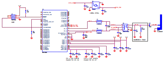
图2.MC1323x系列基本应用电路图 1323x 开发硬件平台 The MC1323x development platform is an IEEE 802.15.4 compliant evaluation environment based on the Freescale MC1323x device. The heart of the MC1323x platform is Freescale’s low cost System-on-Chip (SoC) for the IEEE® 802.15.4 Standard that incorporates a complete, low power, 2.4 GHz radio frequency transceiver with Tx/Rx switch, an 8-bit HCS08 CPU, and a functional set of MCU peripherals into a 48-pin LGA package. This family of products is targeted for wireless RF remote control and other cost-sensitive applications ranging from home TV and entertainment systems such as ZigBee BeeStack Consumer (RF4CE) to low cost, low power, IEEE 802.15.4 and ZigBee end nodes. The MC1323x development platform is comprised of three boards: • 1323x-Modular Reference Board (1323x-MRB) - this board contains the MC1323x device with 32 MHz reference oscillator crystal, RF circuitry including antenna, and supporting circuitry. The board can be used as a simple standalone evaluation platform or as a daughter card to the other MC1323x development platform boards or to a custom, application specific motherboard.. — Provides compact reference design for device footprint and RF layout — Provides pre-designed MC1323x hardware (device and function) — Provides access to the MC1323x full set of GPIO — Provides MCU BDM debug port — Provides optional local 2 Mbit serial FLASH, 32.768 kHz oscillator crystal, IR “blaster” LED and power management. • 1323x-Remote Control Motherboard (1323x-RCM) - this board accepts the 1323x-MRB as a plug-in module (daughter card) and supplies a variety of peripheral functions to the MC1323x through the IO connectors. The peripheral functions are targeted primarily to a consumer TV or entertainment remote control application. — Provides 36-switch matrix for remote control pushbuttons — USB <> serial interface for communication to a PC and provides board power — Touchpad for user interface — Onboard 128 x 32 pixel graphic LCD for menus and host feedback - a unique feature to RF-based remote controls — Accelerometer for motion detection and game play • 1323x-Remote Extender Motherboard (1323x-REM) - this board also accepts the 1323x-MRB plug-in module (daughter card) and supplies a very simple set of peripheral functionality. A small 8-switch matrix, IR receiver, and USB interface provides means for communication to the MC1323x for: — Simple keypad-only applications — Connection to a PC — Host connection such as for a remote control extender or remote control receiver Whether the 1323x-MRB is used in a simple standalone application or in combination with another host card, Freescale provides a complete software development environment called the Freescale BeeKit Wireless Connectivity Toolkit (BeeKit). BeeKit is a comprehensive codebase of wireless networking libraries, application templates, and sample applications. The BeeKit Graphical User Interface (GUI) allows users to create, modify, and update various wireless networking implementations. A wide range of software functionality is available to complement the 1323x-MRB and these are provided as codebases within BeeKit. 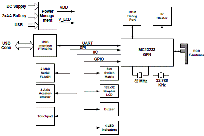
图3.MC1323x系列简化RCM+MRB框图 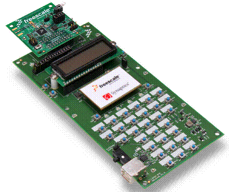
图4.1323x-MRB安装在1323x RCM的外形图 MC1323x开发平台主要特性: • Full IEEE 802.15.4 compliant wireless node; ZigBee capable with Freescale’s BeeStack software stack • Based on Freescale’s low-cost MC1323x IEEE® 802.15.4 SoC platform which incorporates a complete, low power, 2.4 GHz radio frequency transceiver with Tx/Rx switch, an 8-bit HCS08 CPU, and a functional set of MCU peripherals into a 48-pin LGA package • Reference design area with small footprint, low cost RF node Integrated transmit/receive switch — Differential input/output port (typically used with a balun) — Low external component count — Programmable output power with 0 dBm nominal output power, programmable from -30 dBm to +3 dBm typical — Receive sensitivity of -93 dBm (typical) at 1% PER, 20-byte packet, much better than the IEEE 802.15.4 Standard of -85 dBm — Onboard printed metal F-Antenna • 32 MHz reference oscillator • BDM serial MCU debug port • Optional secondary 32.768 kHz crystal oscillator for accurate low power timing • IR blaster • 2 Mbit serial FLASH (uses SPI interface) • Master reset switch • Full power regulation and management • 1323x-MRB board provides — Required circuitry for MC13233 - crystals and RF circuitry including F-Antenna and optional SMA connector — Local power supply regulation — Access to all GPIO — Standalone or daughter card use models — Serial FLASH, IR blaster, and BDM functions • 1323x-RCM when used with 1323x-MRB provides — USB to UART serial interface that is USB bus-powered and full-speed compatible to the USB 2.0 and 1.1 specifications — Power supply source from two AA batteries, USB connector, or DC source — 128x32 pixel graphic LCD — 3-axis Accelerometer (uses IIC interface) — Touch pad interface with interrupt capability (uses IIC interface) — 6x6 Switch matrix — Single tone buzzer — 4 Blue LED indicators • 1323x-REM when used with 1323x-MRB provides — USB to UART serial interface that is USB bus-powered and full-speed compatible to the USB 2.0 and 1.1 specifications — Power supply source from two AA batteries, USB connector, or DC source — IR receiver — 4x2 Switch matrix 4 Blue LED indicators 1323x-MRB参考板 The 1323x-Modular Reference Board (1323x-MRB) is an IEEE 802.15.4 compliant evaluation board based on the Freescale MC1323x device. The 1323x-MRB provides a platform to evaluate the MC1323x device, develop software and applications, and demonstrate IEEE 802.15.4 based networking capabilities. The core device is accompanied by the 32 MHz reference oscillator crystal, RF circuitry including antenna, and supporting circuitry. This basic board is intended as the core module for MC1323x evaluation and application development and can be used in the following modes: • Simple standalone evaluation platform • Daughtercard to the other MC1323x Development Platform boards (1323x-RCM or 1323x-REM) • Daughtercard to an application specific motherboard. 1323x-MRB参考板主要特性: • Small form factor (2 x 2 inches) • 4-Layer metal, 0.034 inch thick FR4 board • MC1323x reference design area — LGA footprint and power supply bypass — 32 MHz reference oscillator crystal — RF components and layout • Low cost RF node — Integrated transmit/receive switch — Differential input/output port (typically used with a balun) — Programmable output power with 0 dBm nominal output power, programmable from -30 dBm to +3 dBm typical — Receive sensitivity of -93 dBm (typical) at 1% PER, 20-byte packet — Printed metal F-Antenna • 32.768 kHz crystal provided for optional timing oscillator • Two connectors provided daughter card mounting — 20-Pin primary connector — 18-Pin secondary connector — Provide main supply voltage to board — Provide access to all MC1323x GPIO • Flexible board power supply — 3.3 V LDO series regulator supplied — Regulator bypass jumper option — Separate external voltage source option — Power-on green LED — Jumpers allow various block current measurements • 6-Pin BDM serial MCU debug port • MC1323x reset switch • Onboard peripheral functions — IR blaster (The MC1323x CMT port is employed as a GPIO to drive large IR blasters. For IR blasters under 20ma, use the CMT port directly.) 2 Mbit serial FLASH (uses SPI interface) 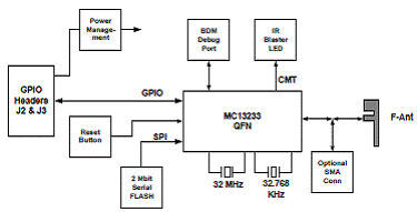
图5.1323x-MRB参考板框图 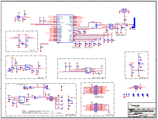
图6.1323x-MRB参考板电路图 1323x-MRB参考板材料清单: 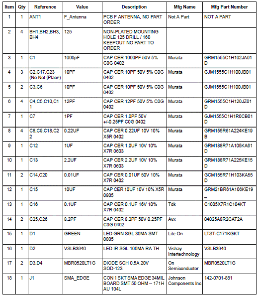
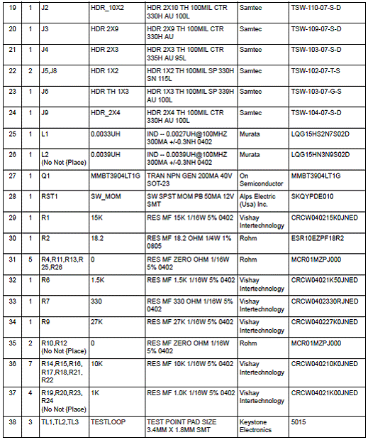
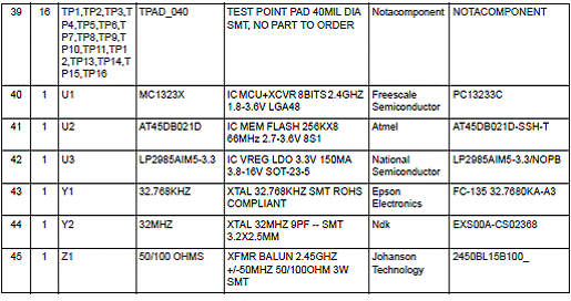
1323x-RCM遥控主板 The Remote Control Motherboard (1323x-RCM) is a motherboard that accepts the 1323x-Modular Reference Board (1323x-MRB) plug-in module (daughter card) and supplies a power supply and a rich set of interface peripherals. The two boards in combination provide a complete platform to evaluate the MC1323x, write software, and develop a full featured IEEE 802.15.4 based wireless remote control. 1323x-RCM遥控主板主要特性: • 4-Layer metal, 0.034 inch thick FR4 board • Two connectors provide daughter card mounting — 20-Pin primary connector — 18-Pin secondary connector — Provide main supply voltage to board — Provide access to all MC13233 GPIO • Handheld battery operation • Flexible power supply — Sources include USB port, two AA batteries, or DC source — Power-On green LED — On-Off switch • Used in conjunction with 1323x-MRB where MRB provides - — 2.4 GHz IEEE 802.15.4 wireless node — 2 Mbit serial FLASH for over-the-air programming (OTAP) — IR blaster • USB interface is bus-powered and full-speed compatible to the USB 2.0 and 1.1 specifications • 36 Pushbutton 6x6 switch matrix • 128x32 pixel monochrome graphic/alphanumeric LCD - uses SPI serial interface • Synaptics® Touchpad™ - capacitive touch sensor • 3-Axis accelerometer with IIC serial interface • Four application-controlled blue indicator LEDs • Single tone buzzer 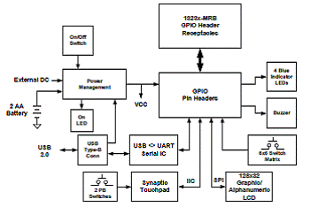
图7.1323x-RCM遥控主板框图 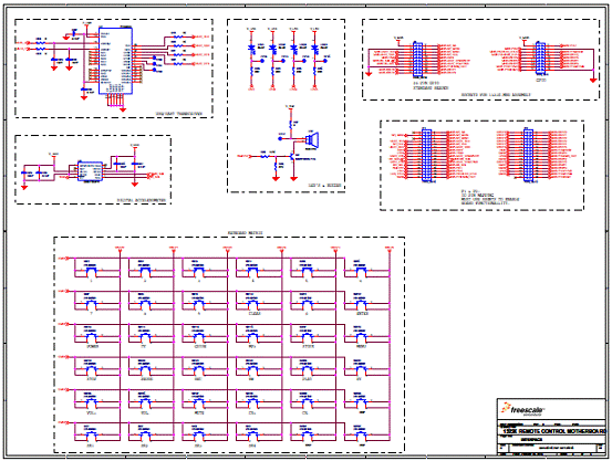
图8.1323x-RCM遥控主板电路图(1) 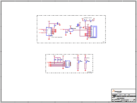
图9.1323x-RCM遥控主板电路图(2) 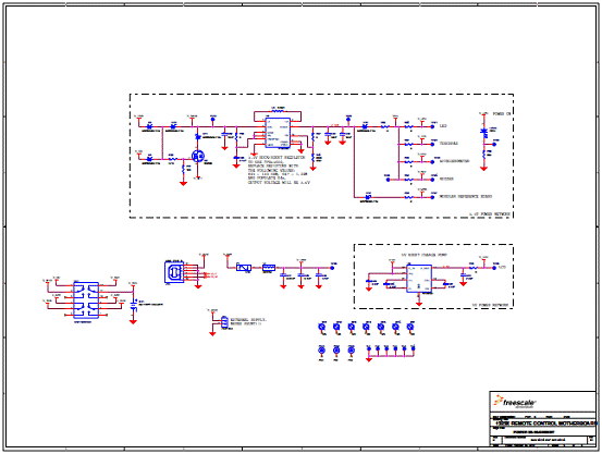
图10.1323x-RCM遥控主板电路图(3) 1323x-RCM遥控主板材料清单: 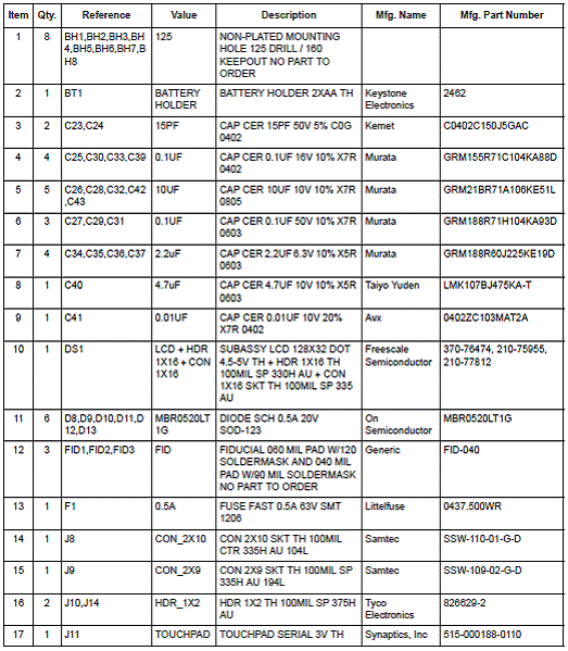
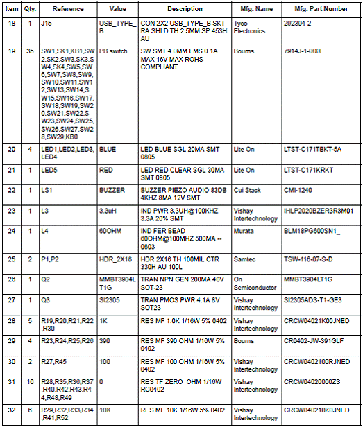
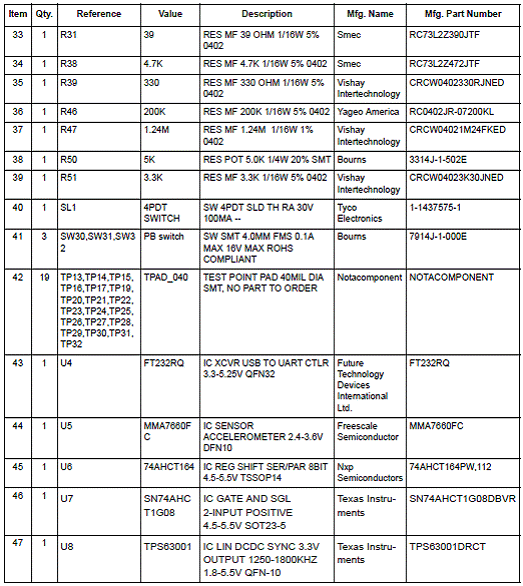

1323x-REM遥控扩展主板 The 1323x-Remote Extender Motherboard (1323x-REM) is a motherboard that accepts the 1323x-Modular Reference Board (1323x-MRB) plug-in module (daughtercard) and supplies a power supply and set of interface peripherals. The two boards in combination provide a simple platform to evaluate the MC1323x, develop software, and demonstrate IEEE 802.15.4 based networking capabilities. 1323x-REM遥控扩展主板主要特性: The 1323x-REM provides the following features: • Small form factor (3.1 x 3.1 inches) • 2-Layer metal, 0.034 inch thick FR4 board • Two connectors provide daughter card mounting — 20-Pin primary connector — 18-Pin secondary connector — Provide main supply voltage to board — Provide access to all MC13233 GPIO • Flexible power supply — Sources include USB port, two AA batteries, or DC source — Power-On LED On-Off switch • USB <> UART serial port • 2x4 Switch matrix • IR receiver • Four application controlled blue indicator LEDs • Secondary set of pin headers uses jumpers to enable/disable IO connections and allows user application connection to MC13233 GPIO 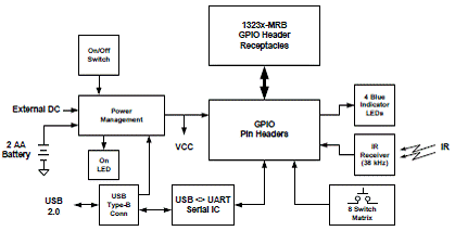
图11.1323x-REM遥控扩展主板框图 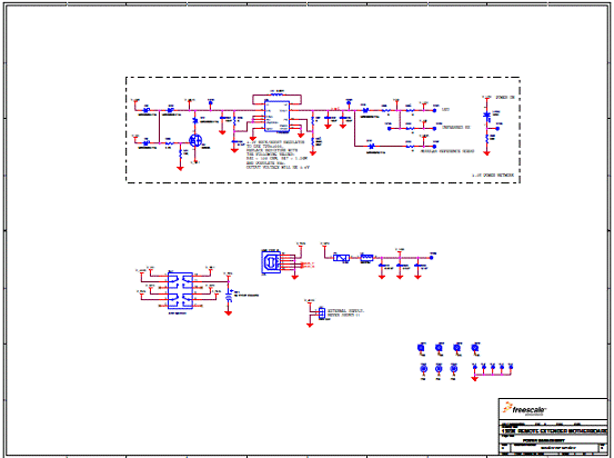
图12.1323x-REM遥控扩展主板电路图(1) 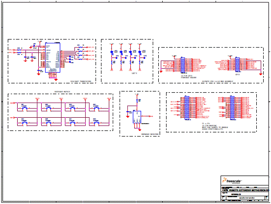
图13.1323x-REM遥控扩展主板电路图(2) 1323x-REM遥控扩展主板材料清单: 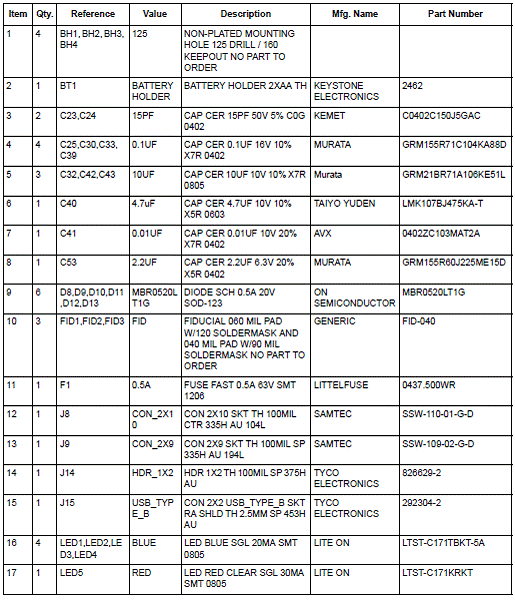
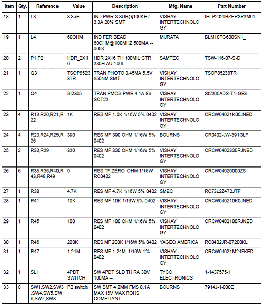

详情请见:  MC1323x[1].pdf
(515.27 KB)
 1323xDHRM[1].pdf
(2.89 MB)
来源:网络 |


网友评论