TI bq25504高效率超低功耗能量采集解决方案~*
发布时间:2011-11-1 11:05
发布者:1770309616
|
TI 公司的bq25504是高效率超低功耗能量采集升压充电IC,可以管理各种直流源如太阳能或热电发生器(TEG)所产生的微瓦或毫瓦功率,超低静态电流小于330nA,可连续从VIN大于80mV的输入源采集能量,冷起动电压VIN大于330mV,具有可编程的动态MPPT,所采集的能量可储存在锂电池,薄膜电池,超级电容或传统电容.主要用于能量采集,太阳能充电器, TEG收集,无线传感器网络(WSN),工业监视,能量存储,环境监测,桥梁/结构健康监测(SHM),智能建筑物控制,手持保健设备以及娱乐系统遥控等.本文介绍了bq25504主要优势和特性,方框图, 太阳能,TEG和MPPT应用电路图,bq25504 EVM评估板性能指标,电路图和材料清单,PCB布局图以及太阳能能量采集总体解决方案包括传统逆变器解决方案框图, 微逆变器解决方案框图和太阳能街灯照明方框图. Texas Instruments introduces highly efficient boost charger IC for nano power energy harvesting The bq25504 is the first of a new family of intelligent integrated energy harvesting Nano-Power management solutions that are well suited for meeting the special needs of ultra low power applications. The product is specifically designed to efficiently acquire and manage the microwatts (μW) to miliwatts (mW) of power generated from a variety of DC sources like photovoltaic (solar) or thermal electric generators. The bq25504 is the first device of its kind to implement a highly efficient boost converter/charger targeted toward products and systems, such as wireless sensor networks (WSN) which have stringent power and operational demands. The design of the bq25504 starts with a DCDC boost converter/charger that requires only microwatts of power to begin operating. bq25504主要优势和特性: • Ultra Low Power With High Efficiency DC/DC Boost Converter/Charger –Continuous Energy Harvesting From Low Input Sources: VIN ≥ 80 mV(Typical) –Ultra Low Quiescent Current: IQ < 330 nA (Typical) –Cold-Start Voltage: VIN ≥ 330 mV (Typical) • Programmable Dynamic Maximum Power Point Tracking (MPPT) – Integrated Dynamic Maximum Power Point Tracking for Optimal Energy Extraction From a Variety of Energy Generation Sources –Input Voltage Regulation Prevents Collapsing Input Source • Energy Storage –Energy can be Stored to Re-Chargeable Li-ion Batteries, Thin-film Batteries, Super-Capacitors, or Conventional Capacitors • Battery Charging and Protection User Programmable Undervoltage /Overvoltage Levels – On-Chip Temperature Sensor with Programmable Overtemperature Shutoff • Battery Status Output –Battery Good Output Pin –Programmable Threshold and Hysteresis –Warn Attached Microcontrollers of Pending Loss of Power –Can be Used to Enable/Disable System Loads bq25504应用: • Energy Harvesting • Solar Charger • Thermal Electric Generator (TEG) Harvesting • Wireless Sensor Networks (WSN) • Industrial Monitoring • Energy Storage • Environmental Monitoring • Bridge / Structural Health Monitoring (SHM) • Smart Building Controls • Portable and Wearable Health Devices • Entertainment System Remote Controls 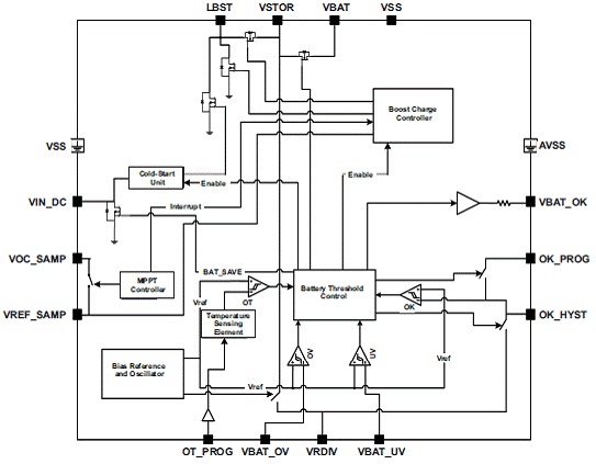
图1.bq25504功能方框图 
图2.bq25504太阳能应用电路图 VIN_DC = 1.2 V, CSTOR= 4.7 μF, LBST= 22 μH, CHVR= 4.7 μF, CREF= 10 nF, TSD_PROTL (65°C), MPPT (VOC) = 80% VBAT_OV = 3.1 V, VBAT_UV = 2.2 V, VBAT_OK = 2.4 V, VBAT_OK_HYST = 2.8 V, ROK1 = 4.42 MΩ, ROK2 = 4.22 MΩ, ROK3 = 1.43 MΩ, ROV1 = 5.9 MΩ, ROV2 = 4.02 MΩ, RUV1= 5.6 MΩ, RUV2 = 4.42 MΩ, ROC1= 15.62 MΩ, ROC2 = 4.42 MΩ 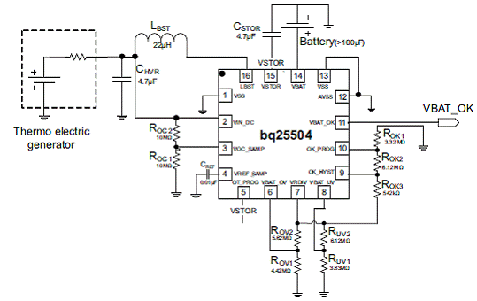
图3.bq25504 TEG应用电路图 VIN_DC = 0.5 V, CSTOR = 4.7 μF, LBST = 22 μH, CHVR = 4.7 μF, CREF = 10 nF, TSD_PROTH (120°C), MPPT (VOC) = 50% VBAT_OV = 4.2 V, VBAT_UV = 3.2 V, VBAT_OK = 3.5 V, VBAT_OK_HYST = 3.7 V, ROK1 = 3.32 MΩ, ROK2 = 6.12 MΩ, ROK3 = 0.542 MΩ, ROV1 = 4.42 MΩ, ROV2 = 5.62 MΩ, RUV1 = 3.83 MΩ, RUV2 = 6.12 MΩ, ROC1 = 10 MΩ, ROC2 = 10 MΩ 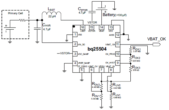
图4.bq25504 MPPT应用电路图 VIN_DC = 1.2 V, CSTOR = 4.7 μF, LBST = 22 μH, CHVR = 4.7 μF, TSD_PROTL (65℃), MPPT (VOC) = Disabled VBAT_OV = 3.3 V, VBAT_UV = 2.2 V, VBAT_OK = 2.8 V, VBAT_OK_HYST = 3.1 V,ROK1 = 3.97 MΩ, ROK2 = 5.05 MΩ, ROK3 = 0.976 MΩ, ROV1 = 5.56 MΩ, ROV2 = 4.48 MΩ, RUV1 = 5.56 MΩ, RUV2 = 4.42 MΩ bq25504 EVM评估板 bq25504 EVM – Ultra Low Power Boost Converter with Battery Management for Energy Harvester Applications bq25504EVM-674 – Ultra Low Power Boost Converter with Battery Management for Energy Harvester Applications. This EVM is programmed from the factory for settings compatible with most MCU’s and 3V coin cell batteries. The EVM is programmed to deliver a 3.1VDC maximum voltage (OV) for charging the storage element and the under voltage is programmed to 2.2VDC. The VBAT_OK indication toggles high when VSTOR ramps up at 2.8VDC and when VSTOR ramps down to 2.4VDC. The user’s guide describes the bq25504 evaluation module (EVM), how to perform a stand-alone evaluation and allows the EVM to interface with the system and host. bq25504 EVM评估板主要特性: Evaluation Module for bq25504 Ultra Low Power Boost Converter/Charger with Battery Management for Energy Harvester Applications Resistor-programmable settings for under voltage, over voltage for flexible battery management Including POTs for fine tuning the settings (not populated) Programmable push-pull output Indication for battery status (VBAT_OK) Test Points for Key Signals Available for Testing Purpose – Easy Probe Hook-up Jumpers Available – Easy to Change Settings 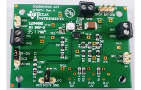
图5. bq25504 EVM评估板外形图 bq25504 EVM评估板性能指标: 
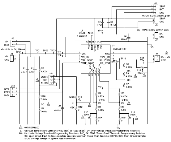
图6. bq25504 EVM评估板电路图 bq25504 EVM评估板材料清单(BOM): 
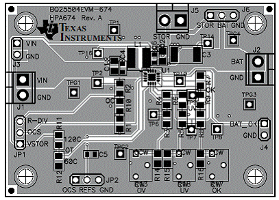
图7. bq25504 EVM评估板PCB布局图 TI 太阳能能量采集总体解决方案 传统逆变器解决方案 Central, or “traditional”, inverters are centralized power control units that convert DC power from a string of 72-cell solar panels to AC power for use on the electrical utility grid. These are usually large scale commercial or residential systems producing in excess of 1 kW of power. Maximum power point tracking for the entire string is done only at the inverter box, which may also include relays to “island” the solar system from the grid. 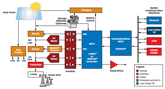
图8.. 传统逆变器解决方案框图 微逆变器解决方案 Micro-inverters operate similarly to central inverter systems, but are installed on each individual panel and handle much less power, typically 300 W. Micro-inverters provide the benefit of scalability for those who want to start small, yet have full DC/AC conversion with MPPT, and expand later. 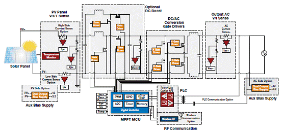
图9.微逆变器解决方案框图(1) Micro-converters maximize the DC power point of a single solar panel and convert (down or up) the DC voltage to be transported downstream to a centralized AC (grid-tied) inverter. Being located on each panel, these systems are lower power (typ. 300 W) than centralized converters. These are sometimes called “optimizers” because they optimize the power of each panel, increasing the overall efficiency of the system. ➔ 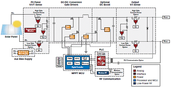
图10.微逆变器解决方案框图(2) 3.电池充电解决方案 Off-grid solar power systems often need to charge a battery, or array of battery cells, that provide continuous power to the load when solar energy is no longer present. Often cost sensitive, in order to optimize the size, cost and usable power of the storage elements, off-grid systems also require that the power point be maximized. However, this can be done by employing, lower power and less complex MCUs than grid-tied systems or by employing a simple fixed power point – often set at 76% of VOC. Loads such as LED lighting and motors may require additional power boosting and/or control. 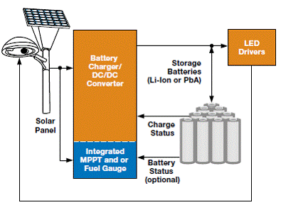
图11.太阳能街灯照明方框图. 详情请见:  bq25504.pdf
(1.08 MB)
 sluu654a.pdf
(753.81 KB)
 slyy027.pdf
(409.79 KB)
|


网友评论