NXP TEA1738GT 65W反激开关电源解决方案
发布时间:2011-10-31 11:32
发布者:Liming
|
NXP公司的TEA1738GT是低成本反激拓扑的开关电源(SMOS)控制器,采用峰值电流和频率控制模式,频率抖动以降低EMI,斜率补偿,具有过功率保胡,输入电压12 V -30 V,适合功率高达75W的高效和低成本电源的各种应用.本文介绍了TEA1738GT主要特性,方框图, 典型配置图, 典型应用电路图以及GreenChip 65 W演示板主要特性,电路图和材料清单与PCB布局图. The TEA1738GT is a low cost Switched Mode Power Supply (SMPS) controller IC intended for flyback topologies. It operates in peak current and frequency control mode. Frequency jitter has been implemented to reduce ElectroMagnetic Interference (EMI). Slope compensation is integrated for Continuous Conduction Mode (CCM) operation. The TEA1738GT IC includes OverPower Protection (OPP). This enables the controller to operate under overpower situations for a limited amount of time. Two pins, VINSENSE and PROTECT, are reserved for protection purposes. Input UnderVoltage Protection (UVP), output OverVoltage Protection (OVP) and OverTemperature Protection (OTP) can be implemented using a minimal number of external components. At low power levels the primary peak current is set to 25 % of the maximum peak current and the switching frequency is reduced to limit switching losses. The combination of fixed frequency operation at high output power and frequency reduction at low output power provides high efficiency over the total load range. The TEA1738GT enables low cost, highly efficient and reliable supplies for power requirements up to 75 W to be designed easily and with a minimum number of external components. The TEA1738GT is intended to operate in combination with a standby power supply. It has a lower start-up voltage than the TEA1738. TEA1738GT主要特性: SMPS controller IC enabling low-cost applications Large input voltage range (12 V to 30 V) Integrated OverVoltage Protection on pin VCC Very low supply current during start-up and restart (10uA typical) Low start-up voltage (13.2 V typical) Low supply current during normal operation (0.55 mA typical no load) Overpower or high/low line compensation Adjustable overpower time-out Adjustable overpower restart timer Fixed switching frequency with frequency jitter to reduce EMI Frequency reduction at medium power operation to maintain high efficiency Frequency reduction with fixed minimum peak current at low power operation to maintain high efficiency at low output power levels Frequency increase at peak power operation Slope compensation for CCM operation Low and adjustable OverCurrent Protection (OCP) trip level Adjustable soft start Two protection inputs (e.g. for input UVP and OTP) IC overtemperature protection TEA1738GT应用: All applications requiring efficient and cost-effective power supply solutions up to 75 W. 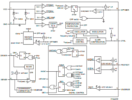
图1.TEA1738GT方框图 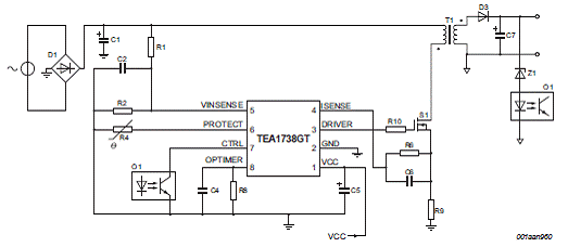
图2.TEA1738GT典型配置图 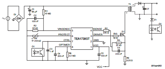
图3.TEA1738GT典型应用电路图 GreenChip 65 W TEA1738LT/T和TEA1703演示板 This 65 W TEA1738LT/T and TEA1703 demo board demonstrates the capabilities of the TEA1738LT/T Switched-Mode Power Supply (SMPS) controller and the TEA1703 standby controller. This manual provides the specification, schematics and PCB layout of the 65 W TEA1738LT/T and TEA1703 demo board. In Standby mode operation (no-load condition), the TEA1703 standby control IC monitors the output voltage and disables the primary controller until the output voltage has reached its lowest preset value. This ensures ultra-low standby power consumption. 
图4.GreenChip 65 W TEA1738LT/T和TEA1703演示板外形图 演示板外形图主要特性: • Universal mains supply operation • OverCurrent Protection (OCP) • OverPower Protection (OPP) • Low ripple and noise • Slim line transformer • Low-cost implementation • Indicator LED • Ultra low no-load standby power (< 50 mW at 230 V, 50 Hz) • ENERGY STAR compliant • EMI CISPR22 compliant 演示板输入指标: 
演示板输出指标: 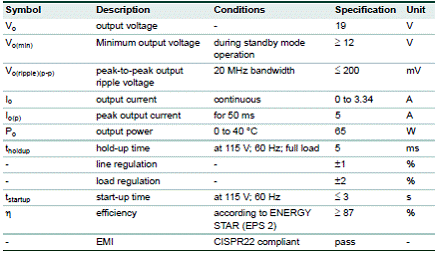
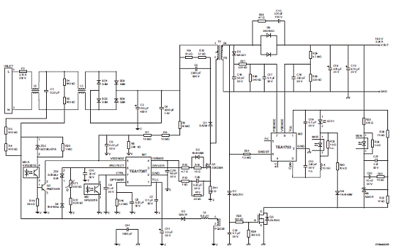
图5.GreenChip 65 W TEA1738LT/T和TEA1703演示板电路图 GreenChip 65 W演示板材料清单: 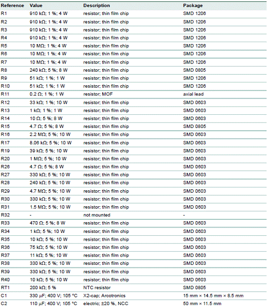
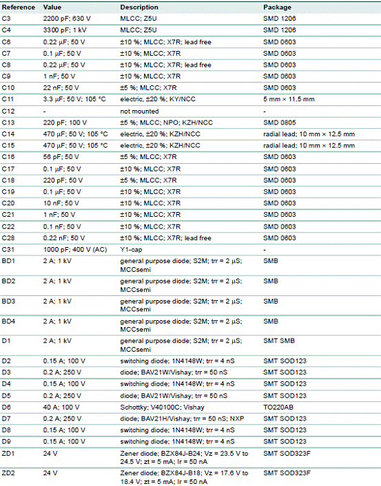
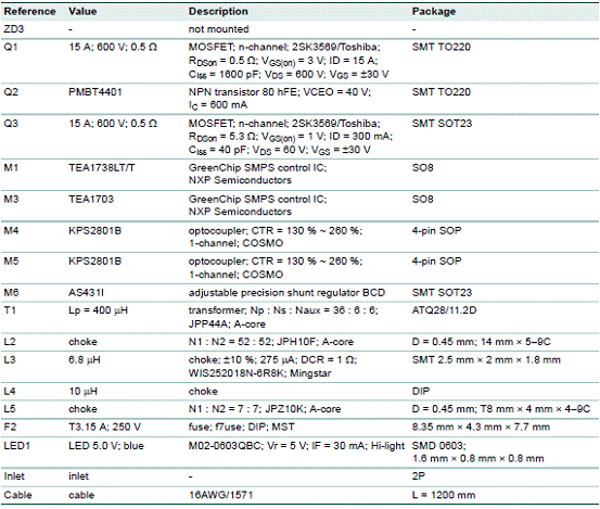
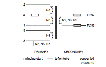
图6.变压器绕组图 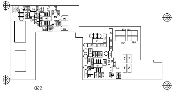
图7.PCB元件布局图(底层) 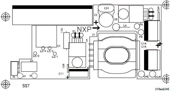
图8.PCB元件布局图(顶层) 详情请见:  TEA1738GT[1].pdf
(195.8 KB)
|




网友评论